Connector

a technology of connecting rods and connectors, applied in the direction of coupling contact members, coupling device connections, instruments, etc., can solve the problems of increasing the size of the housing and hence and achieve the effect of reducing the size of the first housing and the second housing, ensuring electrical contact, and reducing the size of the connector

Active Publication Date: 2012-10-16
NGK INSULATORS LTD
View PDF32 Cites 9 Cited by
  • Summary
  • Abstract
  • Description
  • Claims
  • Application Information

AI Technical Summary

Benefits of technology

[0004]However, if there are such hooks that are orthogonal to the length of contact fittings and bend outward from the contact fittings, the contact fittings need to be widely spaced orthogonally to the length thereof. This increases the size of the housing and hence the size of the connector.
[0005]The present invention has been made to solve the problem described above. A primary object of the present invention is to provide a connector of reduced size.
[0008]In the connector described above, the first housing holds the plurality of long narrow contact fittings arranged at respective positions opposite the plurality of front-surface electrodes of the planar sensor element in the direction substantially orthogonal to the length of the contact fittings, and the second housing holds the plurality of long narrow contact fittings arranged at respective positions opposite the plurality of back-surface electrodes of the planar sensor element in the direction substantially orthogonal to the length of the contact fittings. Each of the contact fittings is obtained by bending a die-cut member having a metal plate portion of substantially rectangular shape and a metal piece connecting to a long side of the metal plate portion. The metal piece is folded to be accommodated within a region directly above a surface of the metal plate portion opposite a surface in contact with the front-surface electrode or the back-surface electrode. Then, the metal piece is bent along the length of the metal plate portion to form a hook to be retained by the first housing or the second housing. Therefore, as compared to a structure in which hooks are orthogonal to the length of metal plate portions and bend outward from contact fittings, the arrangement width of the contact fittings arranged in the direction substantially orthogonal to the length of the contact fittings can be reduced, so that the size of the first housing and the second housing can be reduced. This means that it is possible to reduce the size of the connector.
[0009]The connector according to the present invention may further include regulating members configured to regulate a distance between the first housing and the second housing; and a housing securing member configured to apply pressure to bring the first housing and the second housing closer to each other, with the front-surface electrodes of the sensor element facing the respective conducting portions of the contact fittings on the first housing and the back-surface electrodes of the sensor element facing the respective conducting portions of the contact fittings on the second housing, allow the regulating members to fix the distance between the first housing and the second housing, and clamp and secure the sensor element with pressing force generated by elastic deformation of the conducting portions of the contact fittings on the first housing and the conducting portions of the contact fittings on the second housing. Thus, since the conducting portions clamp the sensor element with pressing force generated by elastic deformation, the conducting portions are less likely to separate from the sensor element. This makes it possible to reliably maintain the electrical contact between the conducting portions and the front-surface electrodes and between the conducting portions and the back-surface electrodes, and to reliably clamp the sensor element. Additionally, since the distance between the first housing and the second housing is fixed by the regulating members, even if excessive pressure is externally applied, the conducting portions are not affected by the pressure and can be prevented from being plastically deformed. It is thus possible to maintain the electrical contact and the clamping of the sensor element for a long period of time, and to ensure longer life of the connector. If a sensor including this connector is used in a vibrating environment, such as in a vehicle, where the connector is often subjected to such excessive pressure, it is particularly useful to apply the present invention. In this case, it is preferable that a spring constant of the conducting portion of each of the contact fittings be in the range of 500 N / mm to 4000 N / mm.

Problems solved by technology

This increases the size of the housing and hence the size of the connector.

Method used


Image

  • Connector
  • Connector
  • Connector

Examples


Embodiment Construction

[0020]Embodiments of the present invention will now be described with reference to the drawings.

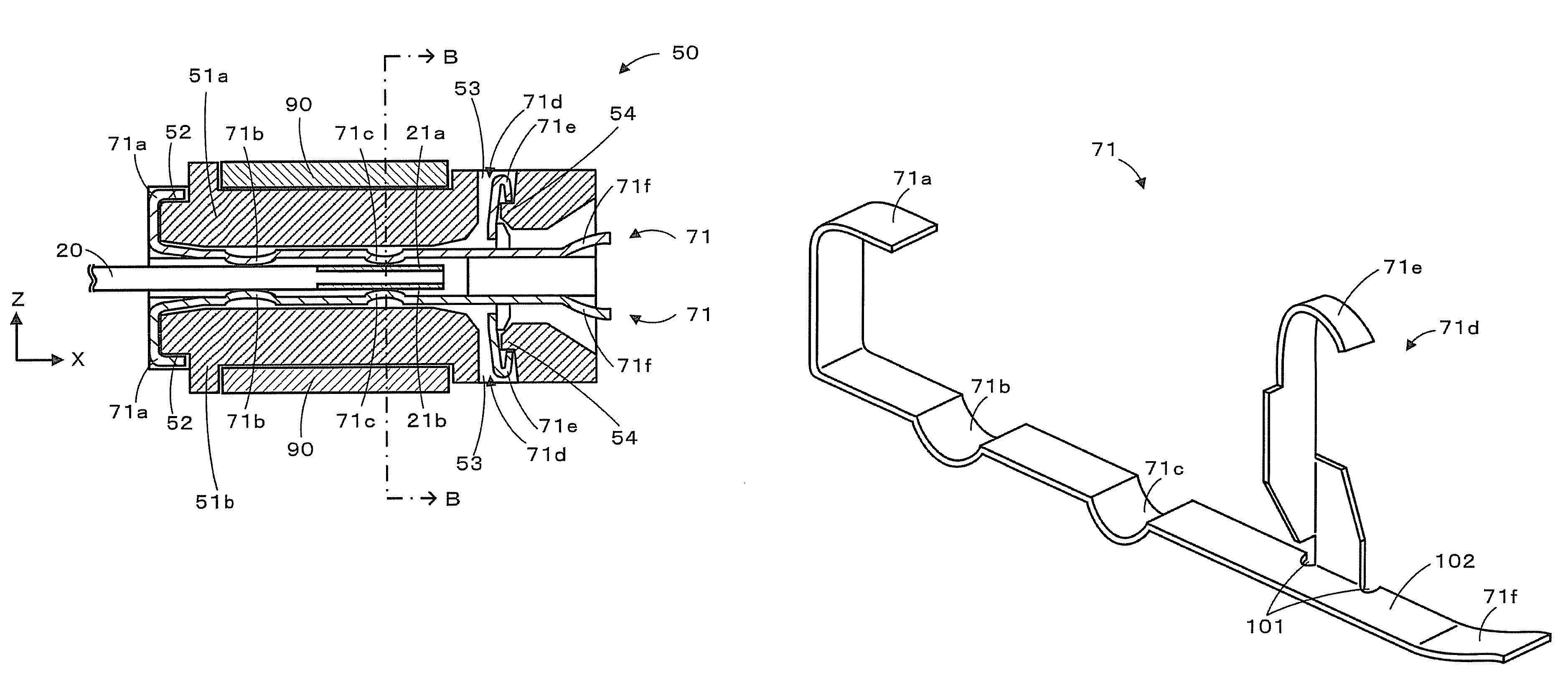
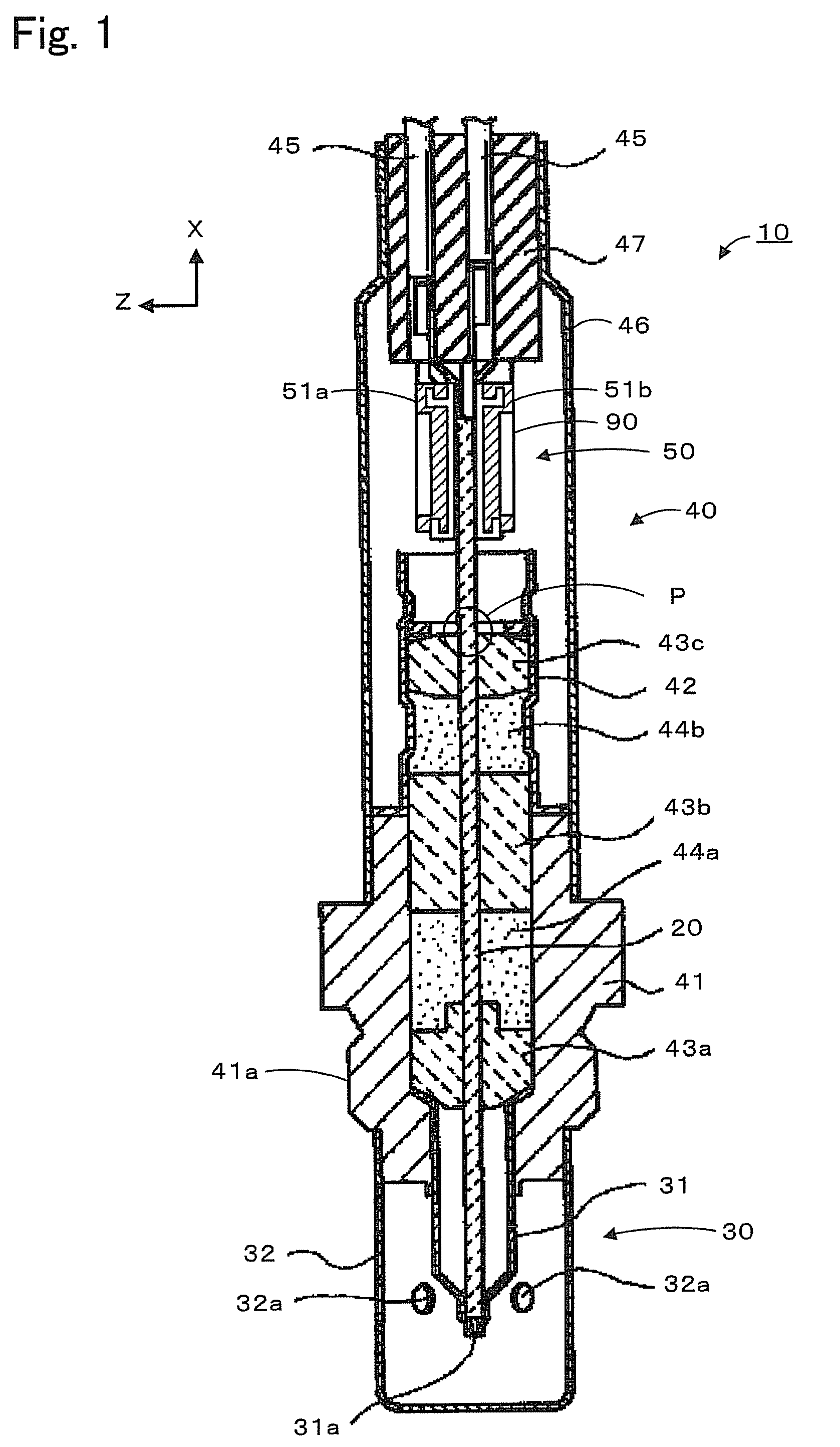
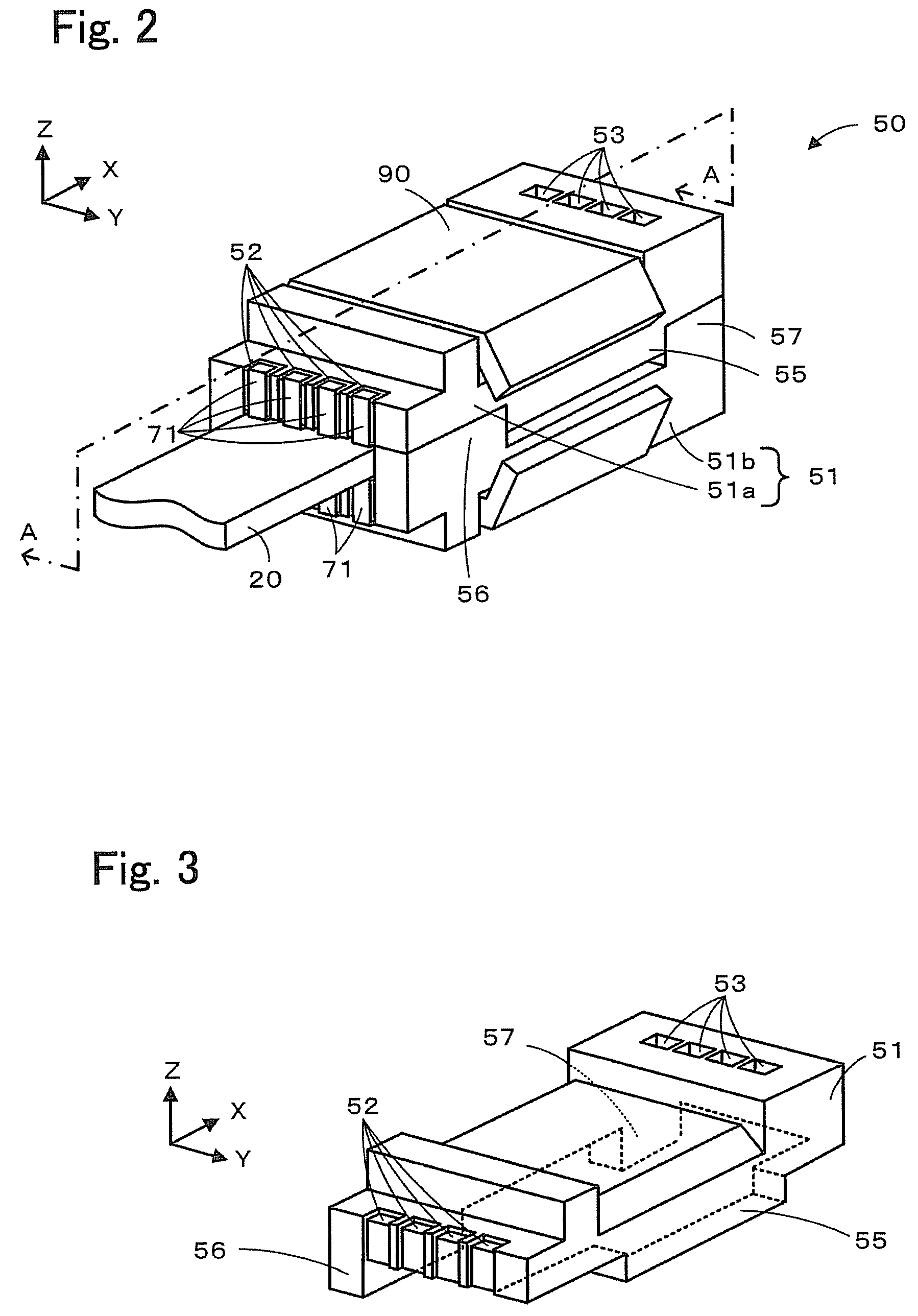
[0021]FIG. 1 is a longitudinal cross-sectional view of a gas sensor 10 according to an embodiment of the present invention. FIG. 2 is a perspective view of a connector 50. FIG. 3 is an exploded perspective view illustrating a housing 51 of the connector 50. FIG. 4 is a cross-sectional view taken along line A-A of FIG. 2. FIG. 5 is a cross-sectional view taken along line B-B of FIG. 4. FIG. 6 illustrates a positional relationship between contact fittings 71 and a sensor element 20 as viewed from a first housing 51a.

[0022]As illustrated in FIG. 1, the gas sensor 10 includes the sensor element 20 that measures a predetermined gas component in gas under measurement, a protective cover 30 that protects an end portion of the sensor element 20, and a sensor assembly 40 that includes the connector 50 electrically connected to the sensor element 20. For example, the gas sensor 10 is attached to a...


PUM


Abstract

Each of contact fittings is obtained by bending a die-cut member having a metal plate portion of substantially rectangular shape and a metal piece connecting to a long side of the metal plate portion. The metal piece is folded to be accommodated within a region directly above a surface of the metal plate portion opposite a surface in contact with a front-surface electrode or a back-surface electrode. Then, the metal piece is bent along the length of the metal plate portion to form a hook to be retained by a first housing or a second housing. Therefore, as compared to a structure in which hooks are orthogonal to the length of metal plate portions and bend outward from contact fittings, the arrangement width of the contact fittings arranged in a direction substantially orthogonal to the length of the contact fittings can be reduced.

Description

TECHNICAL FIELD[0001]The present invention relates to connectors.BACKGROUND ART[0002]Conventionally, a connector has been known which is electrically connected to a plurality of front-surface electrodes arranged side by side on a front surface of a planar sensor element and to a plurality of back-surface electrodes arranged side by side on a back surface of the sensor element. For example, Patent Document 1 describes a gas sensor that includes a planar sensor element configured to detect gas, conductors such as lead wires, and a connector configured to connect the sensor element and the conductors. The connector of the gas sensor includes contact fittings that are electrically connected to the sensor element, and housings that holds the contact fittings. The sensor element is clamped by two housings. FIG. 10 illustrates contact fittings 201a to 201c and a housing 200 of such related art. As illustrated, the contact fittings 201a to 201c are provided with protrusions 202a to 202c, re...

Claims


Application Information

Patent Timeline
Patent Type & Authority Patents(United States)
IPC IPC(8): H01R13/15
CPCG01N27/407H01R13/432H01R12/592
Inventor MASUDA, KOICHIKIYOTA, HIROHITOIKOMA, NOBUKAZU
Owner NGK INSULATORS LTD
Why Eureka
Try Eureka