
Magnetic suspension device

a suspension device and magnetic technology, applied in the field of electromagnetic suspension devices, can solve the problems of limited movement area of the suspension body, increased suspension body, and inconvenient or aesthetic use of the suspension body

Active Publication Date: 2012-10-23
WANG XIAOBING +1
View PDF3 Cites 6 Cited by
  • Summary
  • Abstract
  • Description
  • Claims
  • Application Information

AI Technical Summary

Benefits of technology

[0004]The present invention provides a magnetic suspension device that can realize suspending and rotating the suspension body which is provided with a luminous body. Electric energy is transmitted to the luminous body by wireless method to make the luminous body emit light, thereby making the suspension body to have luminous effect.
[0012]The present invention has the following advantages. The transmitting coil is arranged at the magnetic base, the receiving coil is arranged in the suspension body, wireless power transmission is realized through the transmitting coil and the receiving coil, whereby the luminous body arranged on the suspension body can emit light without any cell and external power supply. This wireless power transmission method can avoid the impact on the operation of the suspension body. The favorable suspension effect of the suspension body is ensured. The suspension body can emit light, and so the decorative effect is very good. The magnetic suspension device can be widely used in fields such as toys, ornaments, advertisements and so on.

Problems solved by technology

While using an external power supply wire, the movable area of the suspension body is limited by the length of the wire, which makes the suspension body is not convenient or aesthetic to be used.
It can avoid limiting the movable area of the suspension body by replacing the power supply wire with a cell to supply the electric power, but the weight of the suspension body is increased, so that the suspension effect is affected, or even the suspension can not be suspended.
Furthermore, if the cell runs out of power, the cell should be changed, which is not convenient in use.

Method used


Image

  • Magnetic suspension device
  • Magnetic suspension device
  • Magnetic suspension device

Examples


Embodiment Construction

[0018]Hereinafter, the present invention is described detailedly with reference to the accompanying figures.

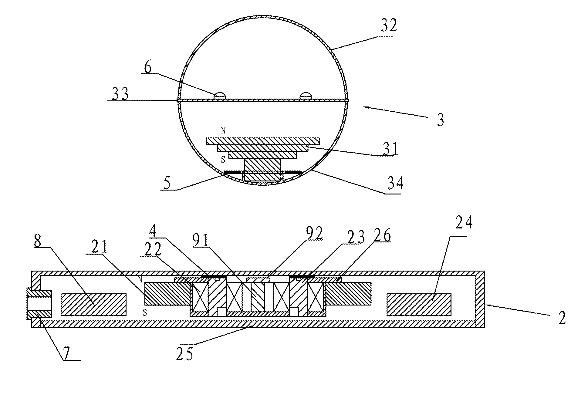
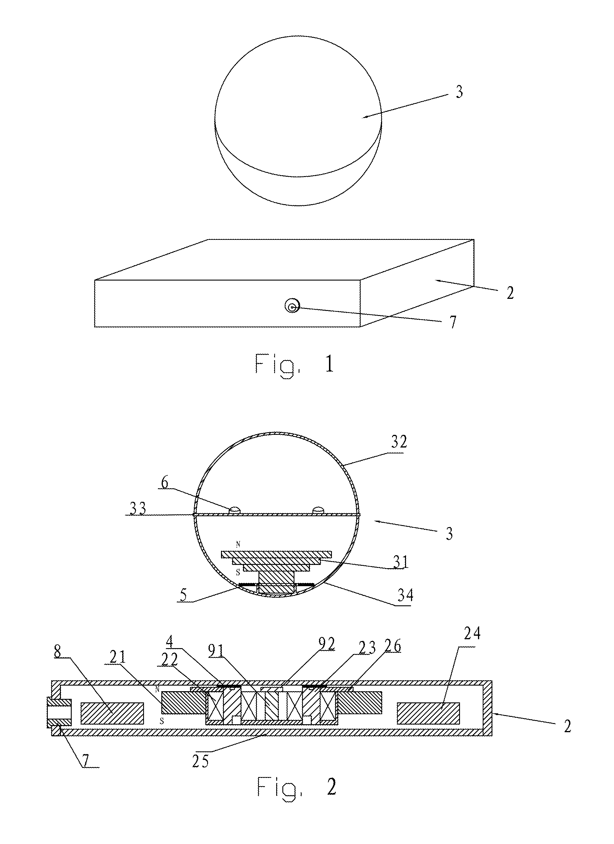
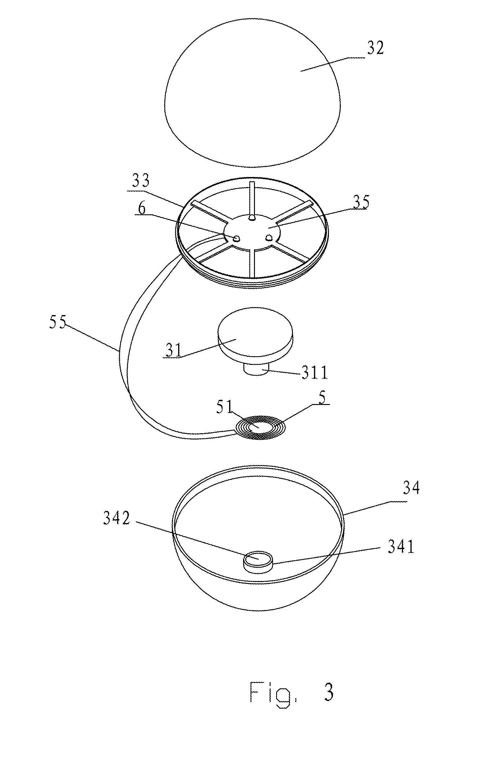
[0019]Referring to FIGS. 1-4, a magnetic suspension device of the present invention comprises a magnetic base 2 and a suspension body 3. Wherein, the suspension body 3 is suspended above the magnetic base 2. The magnetic base 2 is provided with a transmitting coil 4. The suspension body 3 is provided with a receiving coil 5 and at least one luminous body 6. The transmitting coil 4 transmits an AC signal to the receiving coil 5. The receiving coil 5 converts the AC signal transmitted by the transmitting coil 4 into electric energy and supplies the electric energy to the luminous body 6 for emitting light.

[0020]The suspension body 3 is suspended by the balance of the magnetic repulsion between the magnetic base 2 and the suspension body 3. The suspension body 3 comprises at least one permanent magnet arranged at the barycenter vertical of the suspension body 3 or around the bary...


PUM

PropertyMeasurementUnit
electric energyaaaaaaaaaa
magnetismaaaaaaaaaa
magneticaaaaaaaaaa

Abstract

A magnetic suspension device comprises a magnetic base and a suspension body. The suspension body is suspended above the magnetic base. The suspension body is provided with a receiving coil and at least one luminous body. The magnetic base is provided with a transmitting coil. The transmitting coil transmits an AC signal to the receiving coil. The receiving coil converts the AC signal transmitted by the transmitting coil into electric energy and supplies the electric energy to the luminous body for emitting light. In the magnetic suspension device of the present invention, the transmitting coil is arranged at the magnetic base, and the receiving coil is arranged in the suspension body. Wireless power transmission is realized through the transmitting coil and the receiving coil, so, the luminous body arranged on the suspension body can emit light without any cell and external power supply. This wireless power transmission method can avoid the impact on the operation of the suspension body, which not only can ensure the favorable suspension effect of the suspension body, but also can make the suspension body emit light. The magnetic suspension device has a very good decorative effect, and can be widely used in fields such as toys, ornaments, advertisements, and so on.

Description

FIELD OF THE INVENTION[0001]The present invention involves the electromagnetic technical field, particularly involves a magnetic suspension device, of which the suspension body is provided with a luminous body to make the suspension body to have luminous effect.BACKGROUND OF THE INVENTION[0002]A magnetic suspension device has a good decorative effect, and can be widely used in fields such as toys, gifts, advertisements, and so on. A conventional magnetic suspension device generally comprises a magnetic base and a suspension body. An electromagnet mounted inside the magnetic base generates a magnetic repulsion to the suspension body (a magnet is mounted inside the suspension body). The magnetic repulsion is utilized to balance the gravity of the suspension body, so as to make the suspension body to be suspended and rotated.[0003]For making the magnetic suspension device to have a visually aesthetic effect, a luminous body is mounted to the suspension body, thereby making the suspensi...

Claims


Application Information

Patent Timeline
Patent Type & Authority Patents(United States)
IPC IPC(8): H01F7/00
CPCA63H33/26F21S6/002G09F19/02H02N15/00F21V21/00F21W2121/00F21Y2101/02F21Y2115/10
Inventor WANG, XIAOBINGLI, LIANGQING
Owner WANG XIAOBING
Learn More