Supercharge Your Innovation With Domain-Expert AI Agents!

Identifying function-level code dependency by simulating runtime binding

a function-level code and dependency technology, applied in the field of computer software development tools, can solve the problems of affecting the downtime of the affected table, the difficulty of implementing a technique, and the difficulty of altering complex software systems without significantly affecting the availability of the system

Inactive Publication Date: 2012-10-23
GOOGLE LLC
View PDF34 Cites 8 Cited by
  • Summary
  • Abstract
  • Description
  • Claims
  • Application Information

AI Technical Summary

Benefits of technology

The invention is a method for creating a graph data structure for a software system, which includes identifying an entry point and creating nodes and edges connected to each other. Each node represents a class in the software system that can be instantiated, and each edge represents a relationship between the classes. The method also includes identifying functions within the classes that can be invoked when the software system is executed from the entry point. The technical effect of this invention is a more efficient and organized way of creating a software system that can be easily executed and used.

Problems solved by technology

The technical problem addressed in this patent text is the challenge of modifying complex software systems without significantly impacting their availability, particularly for websites and other systems that require high-availability. Existing techniques such as using multiple servers or partitioning the software system have limitations, and identifying the functions and database tables that are used by other functions can be difficult. There is a need for a solution to identify these code and database tables to support partitioning and other types of analyses.

Method used


Image

  • Identifying function-level code dependency by simulating runtime binding
  • Identifying function-level code dependency by simulating runtime binding
  • Identifying function-level code dependency by simulating runtime binding

Examples


Embodiment Construction

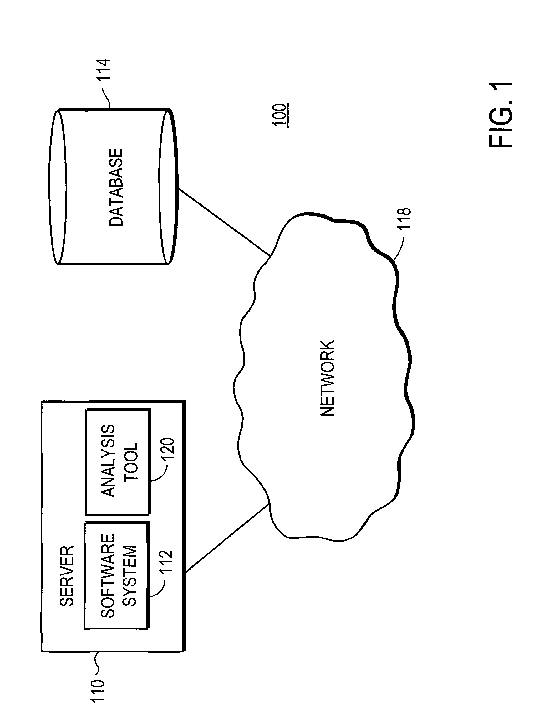
[0017]FIG. 1 is a high-level block diagram illustrating an environment 100 having a server 110 executing a software system 112 according to one embodiment. The software system 112 accesses a database 114. A network 118 provides communications among the server 110 and database 114. In some embodiments, additional servers or databases, and / or other entities such as clients are coupled to the network 118.

[0018]The server 110 includes one or more computers for executing the software system 112. For example, the server 110 can be a standard desktop computer system executing the software system 112, or multiple blade servers working together to execute the software system in a parallel and / or distributed manner. In one embodiment, the database 114 is a relational database having tables with rows and columns that are accessed by the software system 112. As with the server 110, the database 114 includes one or more computers for maintaining and controlling access to it. In one embodiment, t...


PUM


Abstract

An analysis tool analyzes a software system by simulating runtime binding in order to identify function-level code dependencies. The tool receives a list of one or more entry point functions and identifies other functions that can be invoked if the entry point functions are executed. The tool generates a tracker graph having tracker nodes representing classes that can be instantiated from the entry points. Each tracker node identifies functions/methods in that class that can be invoked from the entry points. If the software system uses an object-relational mapping to a database, the tracker graph also identifies the portions of the database that can be accessed from the entry points. The tool can be used to partition the functionalities of the software system into core and non-core functionalities in order to support upgrading while maintaining high-availability.

Description


Claims


Application Information

Patent Timeline
Owner GOOGLE LLC
Features
  • R&D
  • Intellectual Property
  • Life Sciences
  • Materials
  • Tech Scout
  • Unparalleled Data Quality
  • Higher Quality Content
  • 60% Fewer Hallucinations
Learn More