Method, system and computer program product for targeting of a target with an elongate instrument

a target and elongate technology, applied in the field of medical technology, can solve the problems of increasing the risk of tumour seeding, requiring a lot of skill and experience, and increasing the probability of accidental damage of risk structures,

Inactive Publication Date: 2010-03-25
DEUTES KREBSFORSCHUNGSZENT STIFTUNG DES OFFENTLICHEN RECHTS
View PDF11 Cites 106 Cited by
  • Summary
  • Abstract
  • Description
  • Claims
  • Application Information

AI Technical Summary

Benefits of technology

[0023]In the third step, the instrument is to be inserted into the body part. The main task there is to maintain the proper alignment that had been found in the preceding step. In order to achieve this, in the instrument guiding assisting step an image is generated and displayed by which a user can assess whether the motion of the instrument during insertion coincides with the predetermined trajectory. An intuitive way to provide the user with this information is to generate and display an image corresponding to a view of a virtual camera placed at the tip of and directed along the longitudinal axis of the instrument. Simply speaking, in such a virtual view, the user has to steer the instrument during insertion such as to “fly” toward the target in said virtual image. The guiding during the insertion can be further assisted by displaying a tube- or tunnel-li

Problems solved by technology

One of the main challenges related to the intervention is the placement of the instrument at exactly the envisaged position.
As is apparent from the above description, this prior art targeting requires a lot of skill and experience, and in practice, even highly skilled physicians may need several attempts to finally reach the target properly, which makes the patient suffer from the repeated punctures with the elongate instrument as well as multiple exposures to radiation in the necessary control CT scans.
Also, each correction increases the risk of tumour seeding and the pro

Method used


Image

  • Method, system and computer program product for targeting of a target with an elongate instrument
  • Method, system and computer program product for targeting of a target with an elongate instrument
  • Method, system and computer program product for targeting of a target with an elongate instrument

Examples


Embodiment Construction

[0039]For the purposes of promoting an understanding of the principles of the invention, reference will now be made to the preferred embodiment illustrated in the drawings and specific language will be used to describe the same. It will nevertheless be understood that no limitation of the scope of the invention is thereby intended, such alterations and further modifications in the illustrated method and system and such further applications of the principles of the invention as illustrated therein being contemplated as would normally occur now or in the future to one skilled in the art to which the invention relates.

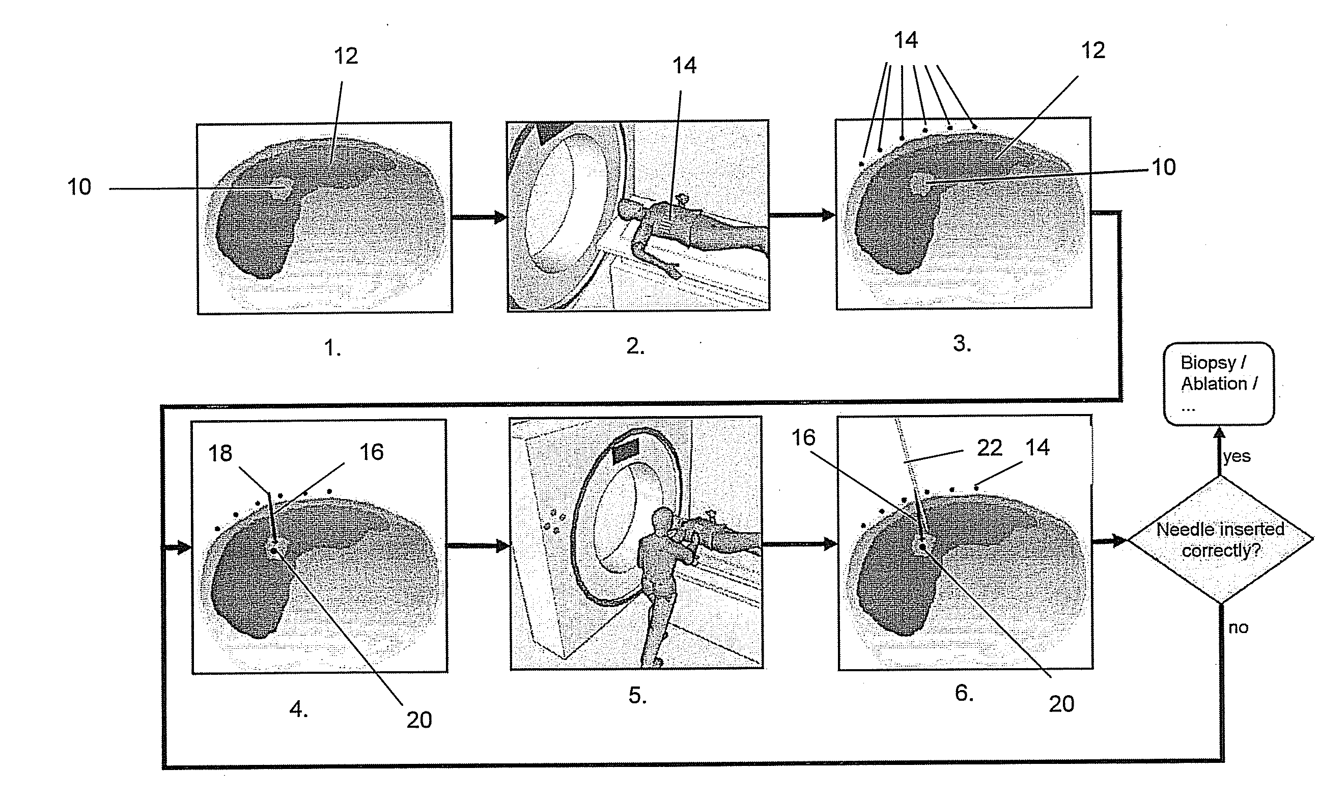
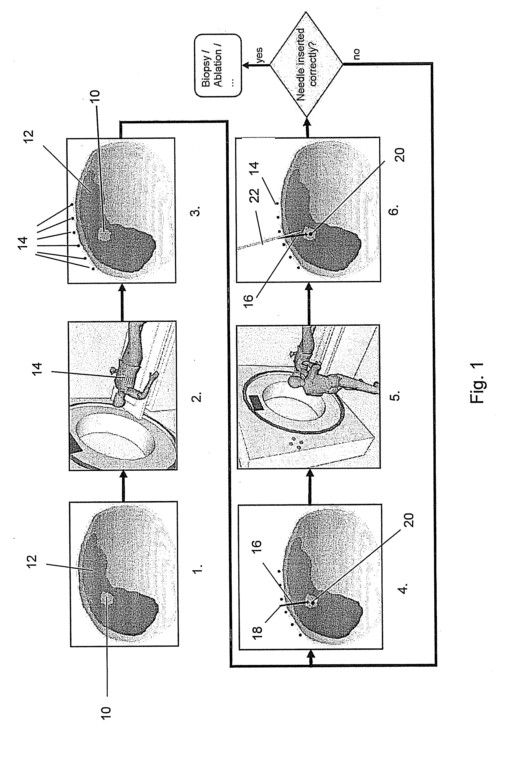
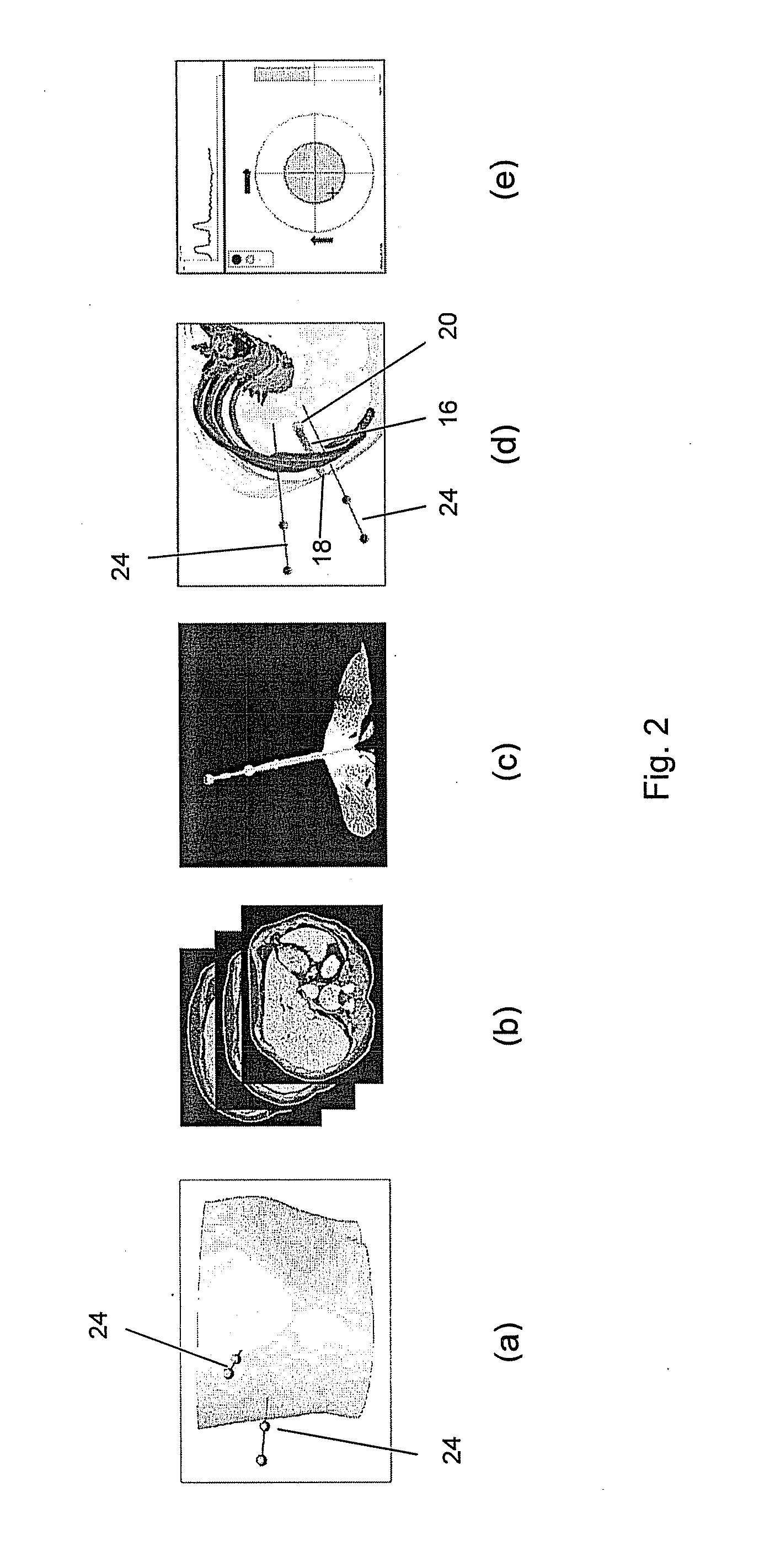
[0040]In (a) to (e) of FIG. 2, the workflow of a minimally invasive intervention is schematically summarized in which the method and system of the invention can be employed. By a way of example only, the intervention is considered to be an ablation of a tumour in a human body's liver. The ablation is done with a needle-like elongate instrument having a tip portion that is...


PUM


Abstract

An embodiment is directed to a method and a system for assisting the targeting of a target with an elongate instrument, wherein the instrument is to be inserted into a living object's body part along a predetermined trajectory extending between an entry point of said instrument into said body part and a target point associated with said target. The method comprises an instrument directing assisting step for generating and displaying an image allowing a user to assess to which extend the longitudinal axis of the instrument is aligned with the vector connecting the target point and the tip portion of said instrument. Also, the method comprises an instrument guiding assisting step of generating and displaying an image allowing a user to assess to which extent the instrument motion during insertion thereof coincides with the predetermined trajectory.

Description

FIELD OF THE INVENTION[0001]The present invention relates to the field of medical technology, and in particular to methods systems for computer assisted targeting of a target in soft tissue.BACKGROUND OF THE INVENTION[0002]Minimally invasive interventions such as biopsies or thermal ablation therapy of certain target areas such as tumours require that an elongate instrument is inserted into a living object's body part such as to exactly reach the target area. The elongate instrument can for example be a biopsy needle or a needle configured for thermal ablation, such as radiofrequency ablation. One of the main challenges related to the intervention is the placement of the instrument at exactly the envisaged position. This is especially true when the target is situated closely to risk structures such as large vessels, further tumours, organs, etc. which must not be hurt by the instrument upon insertion.[0003]With reference to FIG. 1, a common prior art targeting method based on comput...

Claims


Application Information

Patent Timeline
IPC IPC(8): A61B5/05
CPCA61B6/12G06T2207/30021A61B17/3403A61B19/5225A61B19/5244A61B2019/507A61B2019/5236A61B2019/5238A61B2019/524A61B2019/5276A61B2019/5289G01R33/286G01R33/287G06T7/2033G06T2207/10072A61B10/0233A61B34/20A61B90/37A61B2034/107A61B2090/364A61B2090/374A61B2090/376A61B2090/3762A61B2090/378G06T7/246
Inventor MAIER-HEIN, LENASEITEL, ALEXANDERWOLF, IVOMEINZER, HANS PETER
Owner DEUTES KREBSFORSCHUNGSZENT STIFTUNG DES OFFENTLICHEN RECHTS
Why Eureka
Try Eureka