Seal construction for a surface cleaning apparatus

a surface cleaning and construction technology, applied in the direction of filter regeneration, dispersed particle filtration, using liquid separation agents, etc., can solve the problems of reducing the ability to use the surface cleaning apparatus in confined spaces, etc., to increase the weight of reduce the ability to use the surface cleaning apparatus, and the superstructure is larger.

Active Publication Date: 2012-10-30
OMACHRON INTPROP
View PDF19 Cites 51 Cited by
  • Summary
  • Abstract
  • Description
  • Claims
  • Application Information

AI Technical Summary

Benefits of technology

[0006]An advantage of this design is that the mount to secure the component, e.g., the cyclone housing, to the surface cleaning apparatus may be located at a single end. Accordingly locks may be located at the lower end of the component. Therefore, an upper frame or other structure is not required. Typically, the frame of a surface cleaning apparatus is large and provides a recess for the cyclone housing. This frame increases the weight of the surface cleaning apparatus and also creates a larger superstructure, which can decrease the ability to use the surface cleaning apparatus in confined spaces.
[0007]In accordance with this design, the sealing faces of the air inlet and the air outlet may be in different planes. For example, the air outlet seal may be generally horizontal and the air inlet may be at an acute angle to the vertical. Therefore, the air inlet may slide along its mating seal surface as the component is placed on the surface cleaning apparatus and assist in positioning the component in place. In addition, the opposed end of the portion of the surface cleaning apparatus on which the component is mounted, and / or the opposed end of the component, may have a cam member to urge the angled sealing surface of the component to its mating angled sealing surface. This caming action can enhance the air tightness of the resultant seal.

Problems solved by technology

This frame increases the weight of the surface cleaning apparatus and also creates a larger superstructure, which can decrease the ability to use the surface cleaning apparatus in confined spaces.

Method used


Image

  • Seal construction for a surface cleaning apparatus
  • Seal construction for a surface cleaning apparatus
  • Seal construction for a surface cleaning apparatus

Examples


Embodiment Construction

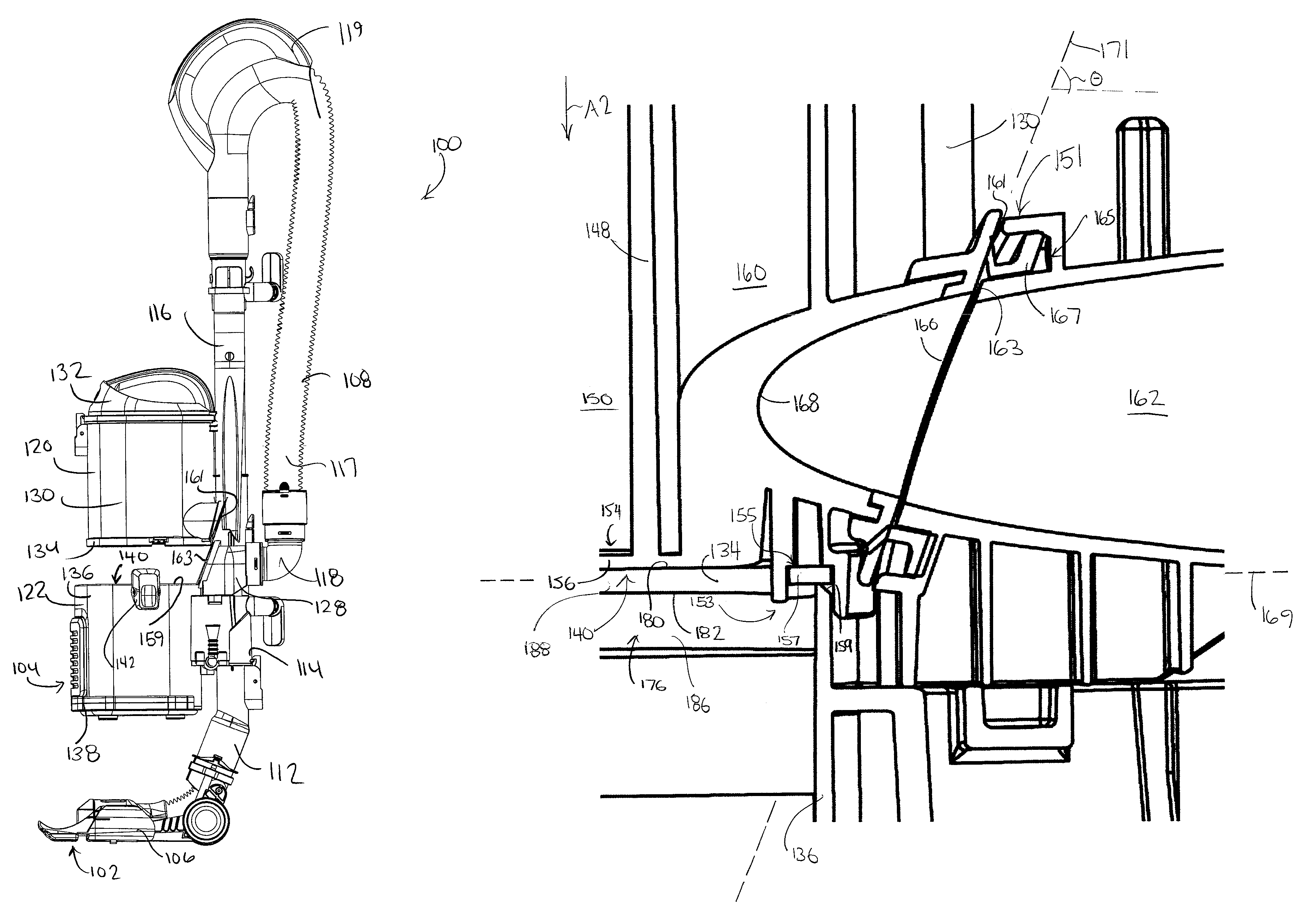
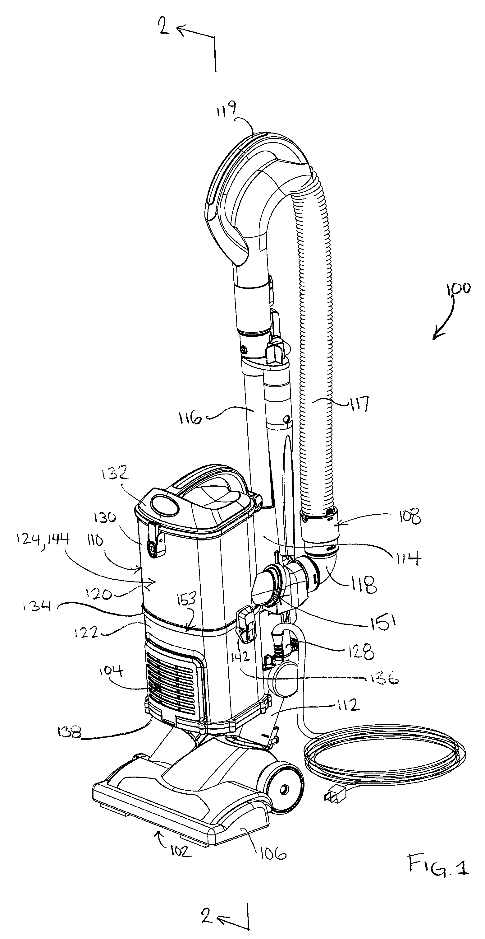
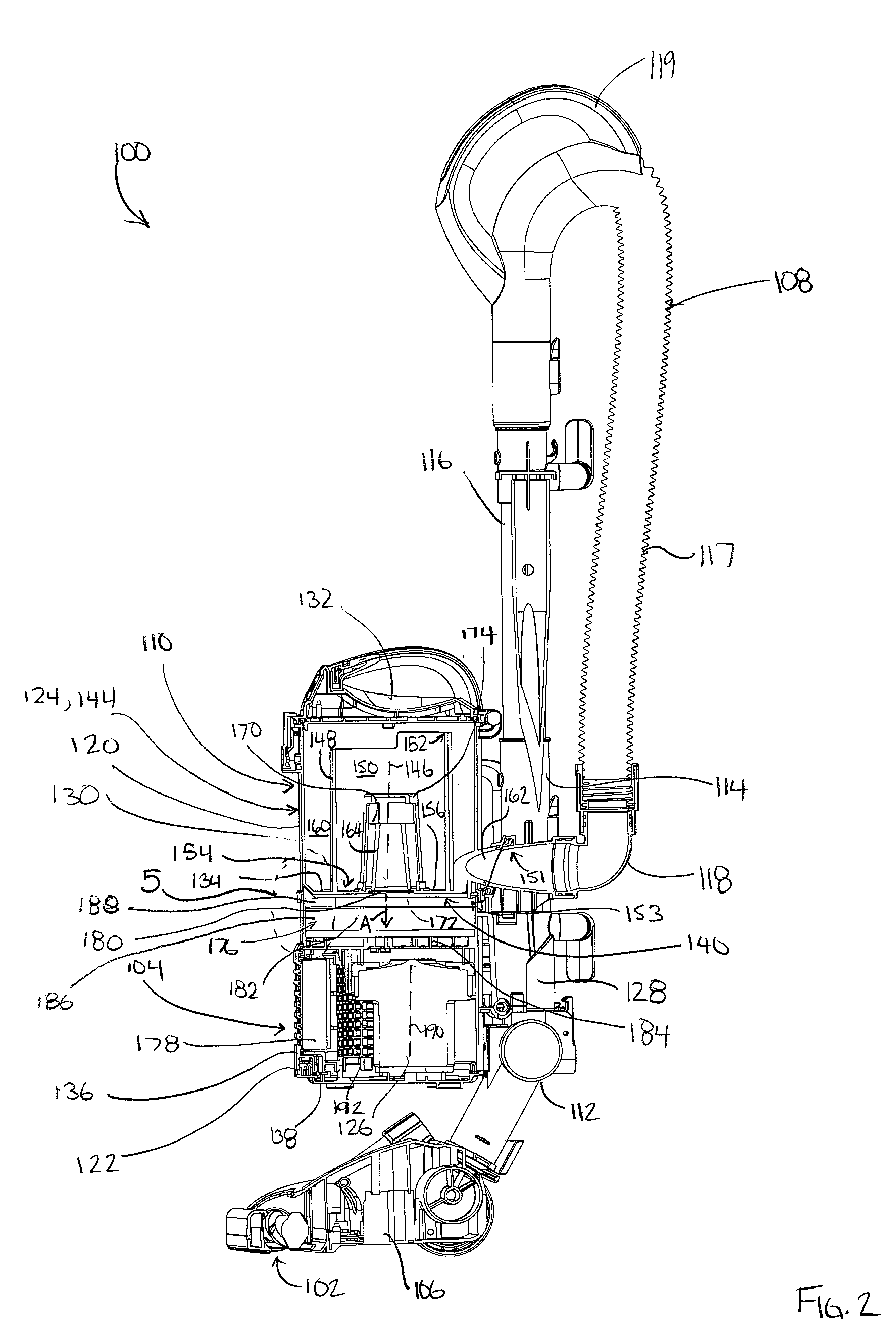
[0038]Referring to FIG. 1, a first embodiment of a surface cleaning apparatus 100 is shown. In the embodiment shown, the surface cleaning apparatus 100 is an upright vacuum cleaner. In alternate embodiments, the surface cleaning apparatus may be another suitable type of surface cleaning apparatus, such as a canister type vacuum cleaner, and hand vacuum cleaner, a stick vac, a wet-dry type vacuum cleaner or a carpet extractor.

[0039]Referring still to FIG. 1, the surface cleaning apparatus 100 has a dirty air inlet 102, a clean air outlet 104, and an air flow passage extending therebetween. In the embodiment shown, the dirty air inlet 102 is provided in a lower surface of a surface cleaning head 106. From the surface cleaning head 106, the airflow passage extends through an air conduit 108, to a suction and filtration unit 110. The clean air outlet 104 is provided in the suction and filtration unit 110. In the embodiment shown, the air conduit 108 includes a pivoting joint member 112 ...


PUM

PropertyMeasurementUnit
angleaaaaaaaaaa
angleaaaaaaaaaa
angleaaaaaaaaaa

Abstract

A surface cleaning apparatus comprises an air flow passage extending from a dirty air inlet to a clean air outlet. A suction motor positioned in the air flow passage. A cyclone is removably mounted to the surface cleaning apparatus and positioned in the air flow path. The cyclone has a cyclone air inlet and a cyclone air outlet. The cyclone is mountable to the surface cleaning apparatus in a mounting direction. An air inlet seal is positioned in a first plane and seals the cyclone air inlet to the airflow passage. An air outlet seal is positioned in a second, non-orthogonal plane and seals the cyclone air outlet to the airflow passage. The air inlet seal and the air outlet seal are concurrently sealed by movement of the cyclone in the mounting direction.

Description

FIELD[0001]The disclosure relates to surface cleaning apparatuses, such as vacuum cleaners. Particularly, the disclosure relates to a surface cleaning apparatus having a removably mounted cyclone and preferably an upright surface cleaning apparatus having a removably mounted cyclone.INTRODUCTION[0002]The following is not an admission that anything discussed below is prior art or part of the common general knowledge of persons skilled in the art.[0003]Various constructions for surface cleaning apparatus such as vacuum cleaners are known. Currently, many surface cleaning apparatus are constructed using at least one cyclonic cleaning stage. The air is drawn into the vacuum cleaner through a dirty air inlet and conveyed to a cyclone inlet. The rotation of the air in the cyclone results in some of the particulate matter in the airflow stream being disentrained from the airflow stream. This material is then collected in a dirt collection chamber, which may be at the bottom of the cyclone ...

Claims


Application Information

Patent Timeline
Patent Type & Authority Patents(United States)
IPC IPC(8): A47L5/14A47L9/10B01D45/12
CPCA47L9/165A47L9/1658
Inventor CONRAD, WAYNE ERNEST
Owner OMACHRON INTPROP
Why Eureka
Try Eureka