Vehicular lamp

a technology for vehicular lamps and lamps, which is applied in the direction of transportation and packaging, semiconductor devices for light sources, lighting and heating apparatus, etc., can solve the problems of uneven brightness, ineffective use of light emitted from the light source, etc., and achieve the reduction of the size of the reflective portion, the effect of reducing the number of parts and reducing the size of the vehicular lamp

Inactive Publication Date: 2012-10-30
KOITO MFG CO LTD
View PDF3 Cites 2 Cited by
  • Summary
  • Abstract
  • Description
  • Claims
  • Application Information

AI Technical Summary

Benefits of technology

[0010]One object of the present invention is to provide a vehicular lamp that makes effective use of light while securing a size reduction and a wide radiation range.
[0013]In some cases, it is possible to make effective use of light emitted from a light source while securing a size reduction and a wide radiation range.
[0014]By effectively using the light, the brightness of the light reflected by the reflector and the brightness of the light reflected by the reflective member can be made uniform to prevent occurrence of uneven brightness.
[0016]Thus, the size of the reflective portion can be reduced to further reduce the size of the vehicular lamp.
[0017]In some embodiments, the control optical section is composed of a lens member that allows the light emitted from the light source to pass through and that guides the light to the cover. Thus, the number of components of the control optical section is small, which contributes to reducing the number of parts and simplifying the structure.
[0018]In some implementations, lens steps are formed on the lens member. Thus, transmitted light can be controlled easily.

Problems solved by technology

Thus, depending on the position and the size of the secondary reflective surface, some of the light that passed through the open portion is not incident on the secondary reflective surface and, therefore, the light emitted from the light source may not be used effectively.
In this case, the brightness of light may be uneven in the radiation range to cause uneven brightness.

Method used


Image

  • Vehicular lamp
  • Vehicular lamp
  • Vehicular lamp

Examples


Embodiment Construction

[0022]In the following paragraphs, preferred modes for carrying out a vehicular lamp according to the present invention are described with reference to the accompanying drawings.

[0023]As described below, the vehicular lamp is applied to a so-called daytime running lamp that is turned on during the daytime to function as a marker lamp. The vehicular lamp is not limited to a daytime running lamp, but is widely applicable to various types of vehicular lamps for use in vehicles such as vehicular headlamps and vehicular marker lamps.

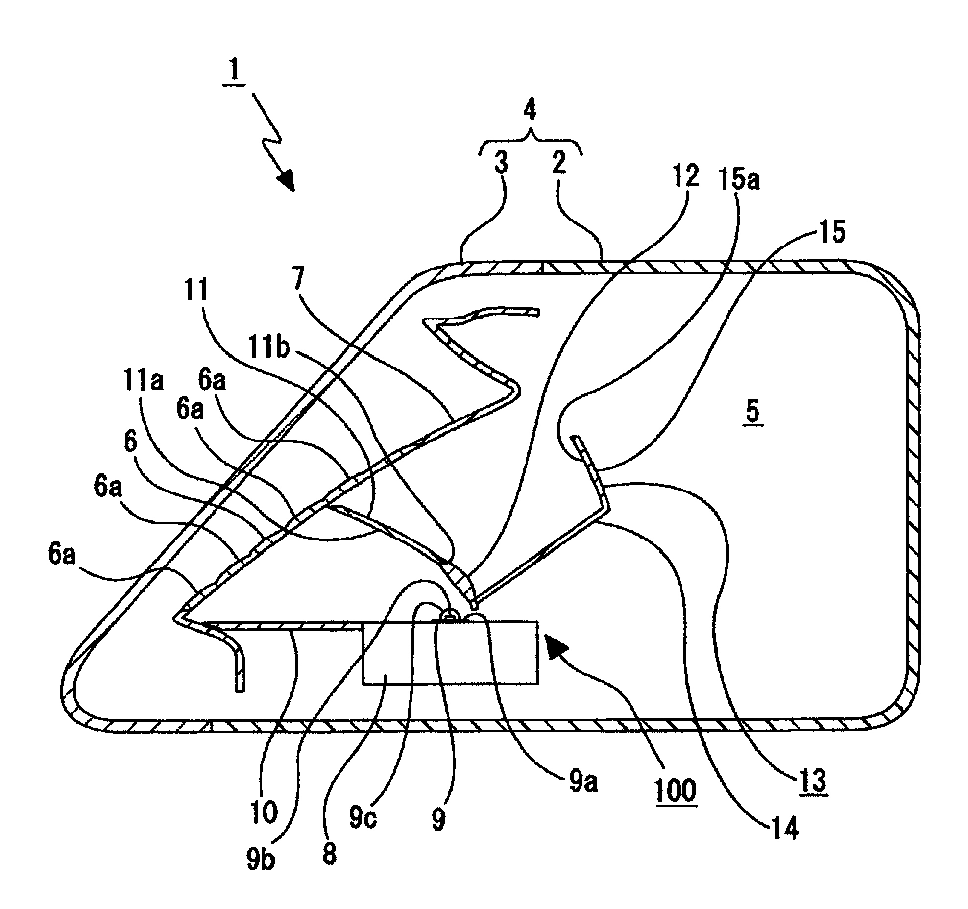
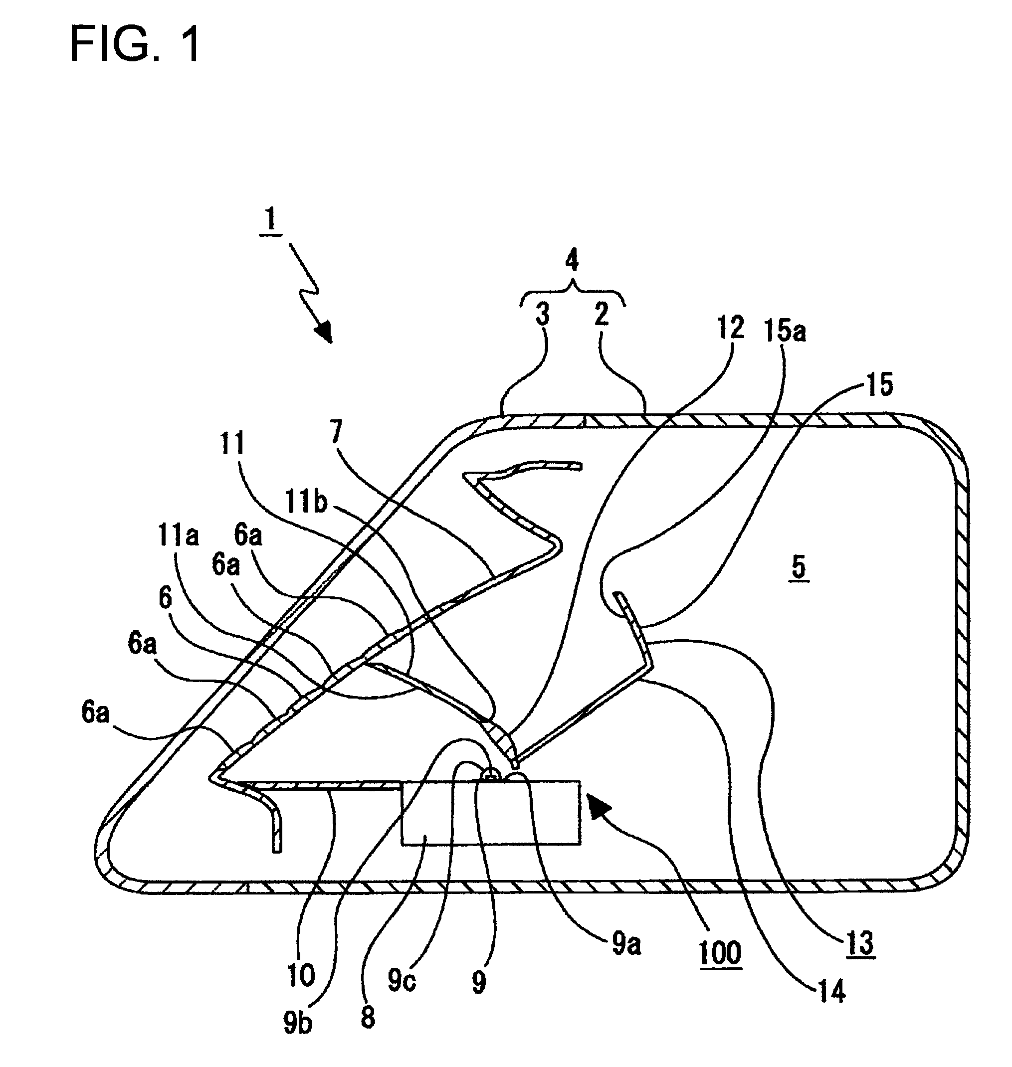
[0024]As shown in FIG. 1, the vehicular lamp (daytime running lamp) 1 includes a lamp housing 2 with an opening on one side and a cover 3 attached to the lamp housing 2 to close the opening. The lamp housing 2 and the cover 3 form a lamp outer housing 4. A lamp chamber 5 is formed inside the lamp outer housing 4.

[0025]In the lamp chamber 5, an inner lens 6 is disposed at a position opposite the cover 3. The inner lens 6 is disposed in an inclined manner. Lens...


PUM


Abstract

A vehicular lamp includes: a lamp outer housing composed of a lamp housing with an opening on one side and a cover attached to the lamp housing to close the opening; a light source disposed inside the lamp outer housing; a reflector that is disposed inside the lamp outer housing, reflects light emitted from the light source, and is formed with an optical path notch or an optical path hole which serves as a path for a part of the light emitted from the light source; and a control optical section having a lens member attached to the reflector so as to close the optical path notch or the optical path hole, and controlling light emitted from the light source toward the optical path notch or the optical path hole to guide the light in a predetermined direction for radiation.

Description

CROSS-REFERENCE TO RELATED APPLICATION[0001]This application claims the benefit of priority of Japanese Patent Application No. 2009-156888, filed on Jul. 1, 2009, the contents of which are incorporated by reference herein.BACKGROUND[0002]1. Technical Field[0003]The present disclosure relates to a vehicular lamp. More particularly, the present disclosure relates to a vehicular lamp having a control optical section with a lens member that closes a reflector in which an optical path notch or an optical path hole is formed. This arrangement makes effective use of light while securing a size reduction.[0004]2. Related Art[0005]Some vehicular lamps include a lamp outer housing composed of a lamp housing and a cover that closes an opening of the lamp housing, a light source inside the lamp outer housing, and a reflector inside the lamp outer housing to reflect light emitted from the light source to guide the light in a predetermined direction.[0006]Some such vehicular lamps are configured ...

Claims


Application Information

Patent Timeline
Patent Type & Authority Patents(United States)
IPC IPC(8): F21V7/04
CPCF21V5/008F21V13/04B60Q2400/30F21S48/115F21S48/125F21V5/04F21Y2101/02F21Y2115/10F21S41/141F21S41/25
Inventor HARA, RYOSUKE
Owner KOITO MFG CO LTD
Why Eureka
Try Eureka