RF plug connector, RF receptacle connector, and RF connector

a technology of rf receptacle and rf plug, which is applied in the direction of coupling device connection, two-part coupling device, electrical apparatus, etc., can solve the problems of remarkable reflection in the soldered portion, and the impedance matching of the connector was not performed, so as to achieve accurate and reliable impedance control, easy impedance matching, and easy impedance matching

Inactive Publication Date: 2012-10-30
THE FUJIKURA CABLE WORKS LTD
View PDF14 Cites 12 Cited by
  • Summary
  • Abstract
  • Description
  • Claims
  • Application Information

AI Technical Summary

Benefits of technology

[0016]In the connector according to the present invention, matching of impedance is easy in the portion between the terminal portion and the coaxial portion since the lead portions of the coaxial portion are arranged on both sides of the lead portion of the terminal portion, and impedance control is performed by adjusting the distance between the lead portion of the terminal portion and the lead portions of the coaxial portion. As a result, it is possible to achieve a structure that is advantageous for use in the high-frequency range by suppressing the generation of signal reflections in the portion.
[0017]Further, the receptacle connector is constituted by the receptacle-side signal contact portion and the receptacle-side ground shell portion being integrated so that the terminal portion is arranged in the center of the coaxial portion, and the lead portion of the signal contact portion is arranged between the pair of lead portions that are provided in the ground shell portion and that extend in the same direction. Also, the plug connector is constituted by the plug-side signal contact portion and the plug-side ground shell portion being integrated so that the terminal portion is arranged in the center of the coaxial portion, and the lead portion of the signal contact portion is arranged between the pair of lead portions that are provided in the ground shell portion and that extend in the same direction. Thereby, it is possible to perform impedance control by adjusting the distance between the lead portions, i.e., between either of the lead portions of the receptacle connector and the lead portions of the plug connector. As a result, matching of impedance is easy in both the receptacle connector and the plug connector, and it is possible to achieve a structure that is advantageous for use in the high-frequency range by suppressing the generation of signal reflections in these portions.
[0018]Moreover, since the lead portions of the signal contact portions and the lead portions of the ground shell portions are flush, it is possible to accurately and reliably perform impedance control by adjustment between the lead portions, which is advantageous in the high-frequency range. Accordingly, it is possible to significantly improve the high-frequency characteristic (VSWR). Further it is possible to enable use in a higher-frequency range (for example 16 GHz) than previously.
[0019]Moreover, if the one surface of the lead portions according to the present invention serves as soldered surfaces, it is possible to perform impedance matching of the soldered portions while maintaining the soldering strength and achieve excellent high-frequency characteristic, compared to a conventional RF connector.

Problems solved by technology

However, in the conventional RF connector, since the distance of the lead attachment portion is short, impedance matching thereof was not performed.
However, in a conventional RF connector, as stated above, remarkable reflection occurred in the soldered portions due to impedance matching of the soldered portions not being particularly performed.

Method used


Image

  • RF plug connector, RF receptacle connector, and RF connector
  • RF plug connector, RF receptacle connector, and RF connector
  • RF plug connector, RF receptacle connector, and RF connector

Examples


Embodiment Construction

[0029]Hereinafter, an RF connector according to an embodiment of the present invention shall be described.

[0030]Note that the embodiment is described in detail in order to better comprehend the gist of the invention, and unless otherwise noted, shall not serve to limit the present invention.

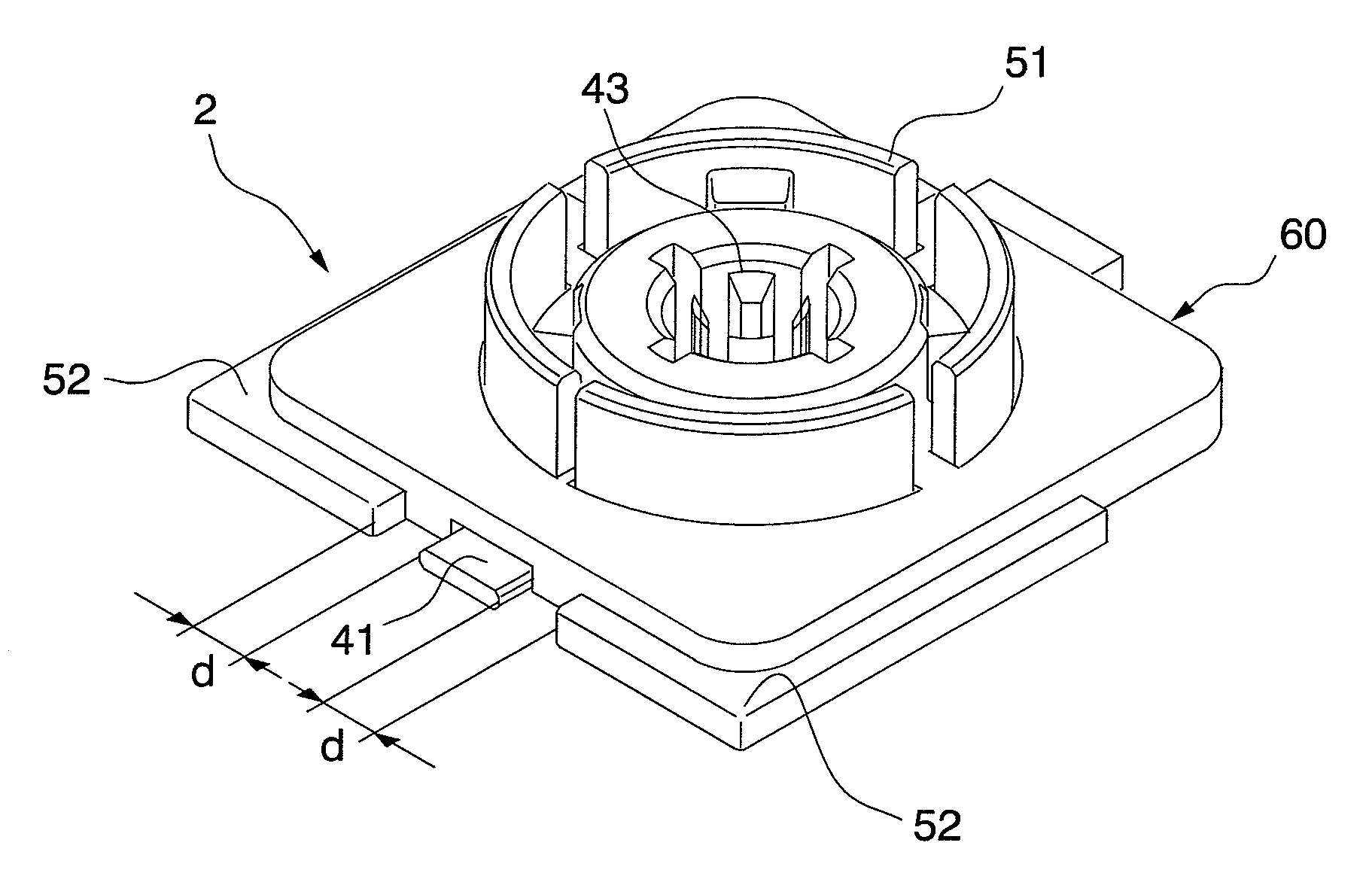
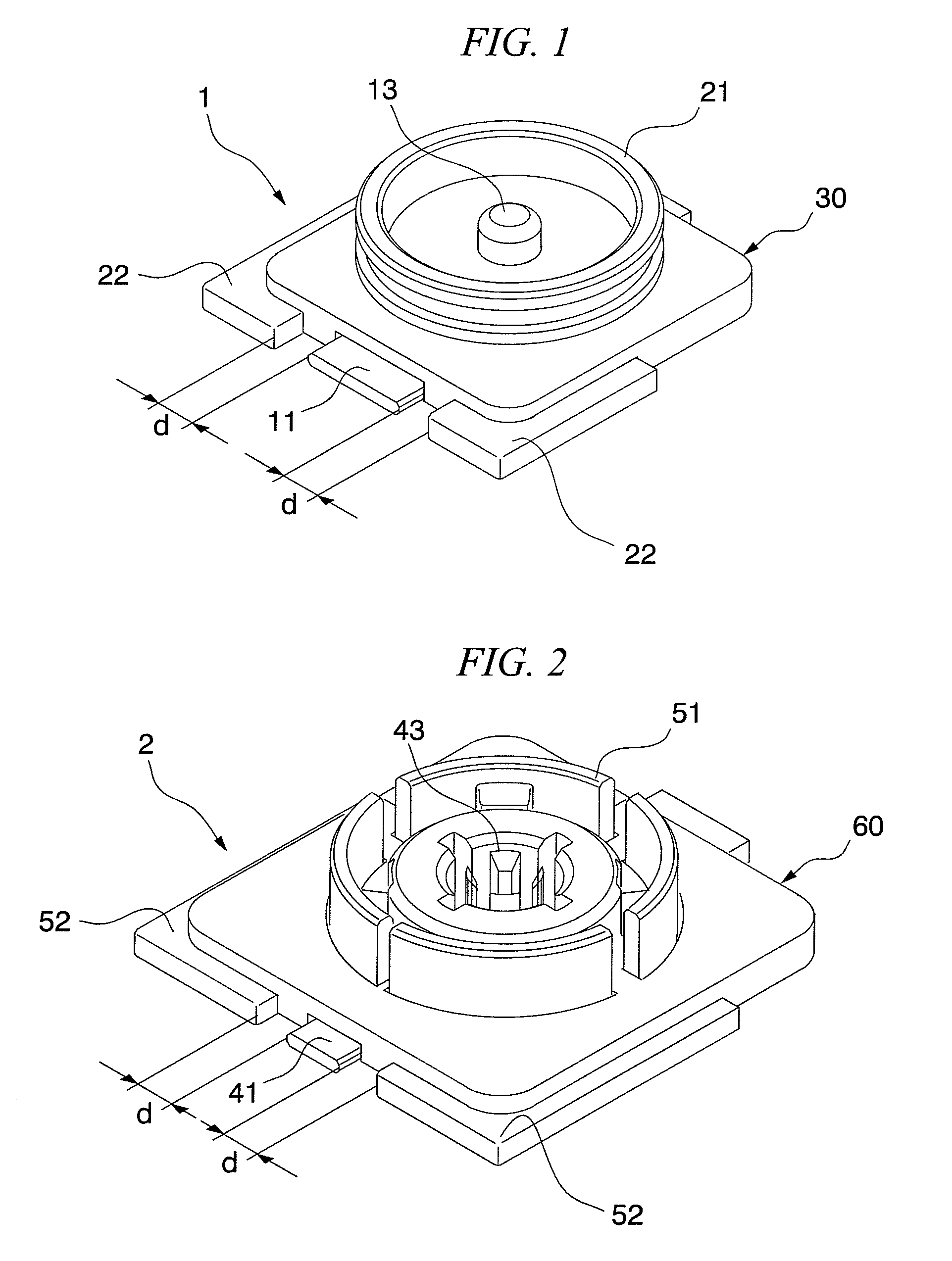
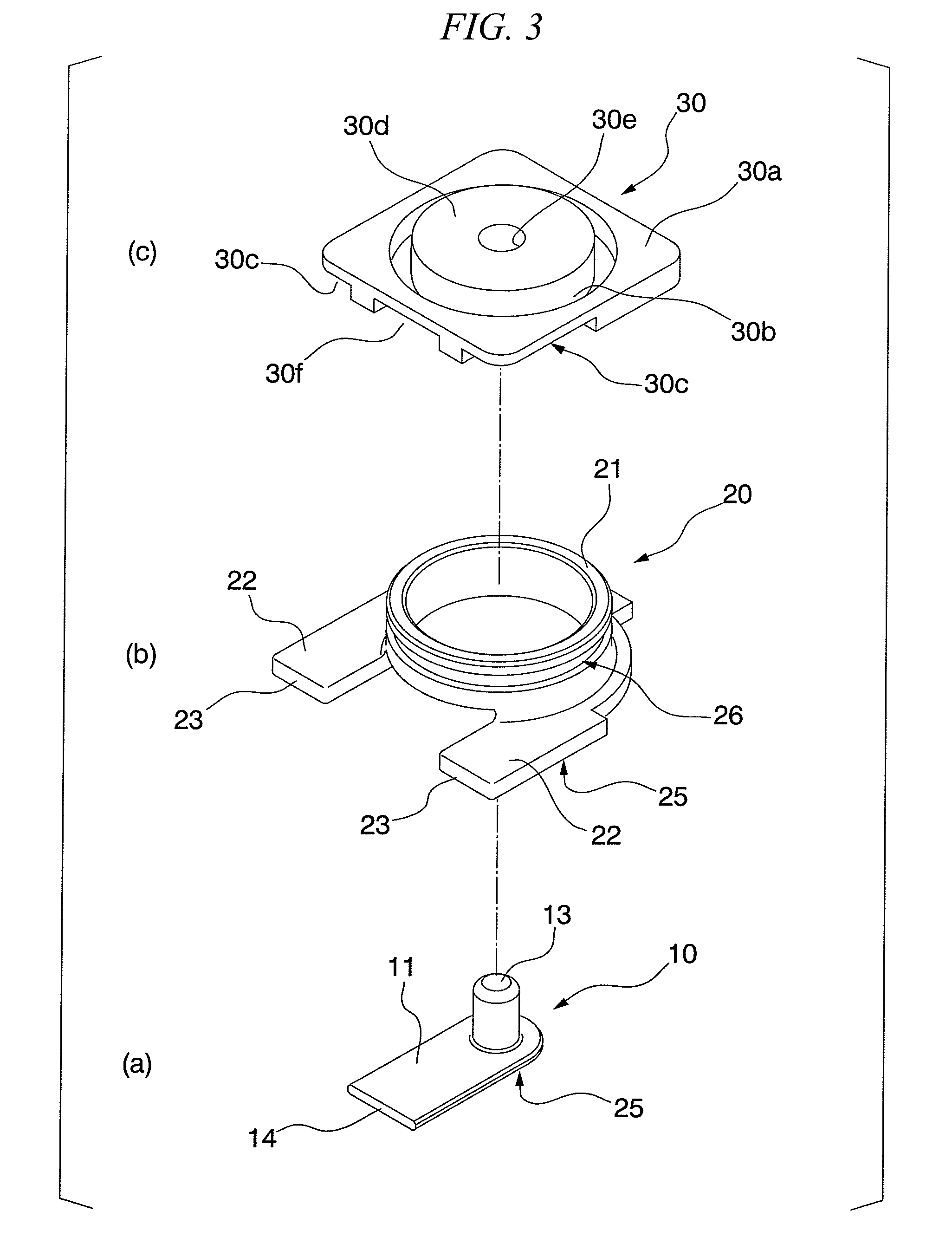
[0031]FIG. 1 and FIG. 2 are figures that show outlines of the RF connector according to the embodiment of the present invention. The RF connector of the present embodiment consists of a receptacle connector 1 and a plug connector 2. The receptacle connector 1 and the plug connector 2 are mounted on separate circuit boards. When the receptacle connector 1 and the plug connector 2 are integrally joined, the substrates on which the connectors are mounted become electrically connected. FIG. 3 and FIG. 4 show schematic exploded perspective views of the receptacle connector 1 and the plug connector 2.

[0032]The receptacle connector 1 is constituted from a receptacle-side signal contact portion 10 shown ...


PUM


Abstract

Provided is an RF plug connector which includes: a conductive terminal portion; and an annular conductive coaxial portion that is arranged around the terminal portion, wherein a pair of conductive lead portions extending in the same direction is provided at the outer circumference of the coaxial portion, the terminal portion comprises a lead portion that is arranged between the pair of lead portions so as to be parallel to an extension direction thereof, and impedance control is performed by adjusting the distance between the lead portion of the terminal portion and the lead portions of the coaxial portion.

Description

CROSS REFERENCE TO RELATED APPLICATIONS[0001]This application is a continuation application based on a PCT Patent Application No. PCT / JP2010 / 000559, filed Jan. 29, 2010, whose priority is claimed on Japanese Patent Application No. 2009-020264 filed Jan. 30, 2009, the entire content of which are hereby incorporated by reference.BACKGROUND OF THE INVENTION[0002]1. Field of the Invention[0003]The present invention relates to a structure of a connector for connecting an RF module and an antenna in an internal component of an electronic device, and relates to a structure of a connector in which the high-frequency characteristics are improved compared to a conventional connector, and further high-frequency response is possible.[0004]2. Description of the Related Art[0005]As a type of coaxial connector, a coaxial connector is known in which an annular space and a cable housing portion are in communication, a cable is exposed in the annular space, the distal end of a cylindrical portion of ...

Claims


Application Information

Patent Timeline
Patent Type & Authority Patents(United States)
IPC IPC(8): H01R9/05H01R13/646
CPCH01R13/6473H01R24/50H01R13/6474H01R13/6471H01R2103/00
Inventor TAGUCHI, HIROYUKI
Owner THE FUJIKURA CABLE WORKS LTD
Why Eureka
Try Eureka