Image sensing apparatus

a technology of image sensing and image data, which is applied in the field of image sensing apparatus, can solve the problems of poor spatial resolution of still image data generated from still image shooting, poor temporal resolution of still image obtained from movie data, and poor spatial resolution of still image data, so as to improve the simultaneity of accumulation, reduce frame rate, and high spatial resolution

Active Publication Date: 2012-10-30
CANON KK
View PDF13 Cites 3 Cited by
  • Summary
  • Abstract
  • Description
  • Claims
  • Application Information

AI Technical Summary

Benefits of technology

[0016]The present invention provides for obtaining a still image with high spatial resolution that improves the simultaneity of accumulation while suppressing a decrease in frame rate.
[0018]The present invention can obtain a still image with high spatial resolution that improves the simultaneity of accumulation while suppressing a decrease in frame rate.

Problems solved by technology

When capturing a movie with an image sensor, the image sensing apparatus requires an electronic shutter function to control the exposure of the image sensor because it is difficult to use a mechanical shutter.
In this case, still image data generated from a movie image does not satisfy the number of pixels requested of still image shooting.
A still image obtained from the generated still image data is poor in spatial resolution.
A movie obtained from the movie data is poor in temporal resolution.
This may impair the simultaneity of accumulation of 1-frame still image data between pixels.

Method used


Image

  • Image sensing apparatus
  • Image sensing apparatus
  • Image sensing apparatus

Examples


first embodiment

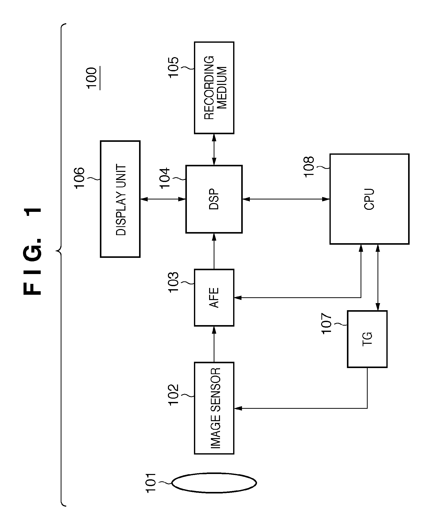
[0055]The image sensing apparatus 100 employs a simultaneous electronic shutter function as an electronic shutter function. The image sensing apparatus 100 includes the following constituent elements.

[0056]An imaging lens 101 forms the optical image of an object on the image sensing surface (pixel array) of an image sensor 102.

[0057]The image sensor 102 converts an optical image formed on the image sensing surface (pixel array) into an image signal. The image sensor 102 reads out the converted image signal from the pixel array, and outputs it. The image sensor 102 is, e.g., a CMOS image sensor.

[0058]A CPU 108 receives an instruction from the user via an operation member (not shown) such as a shutter button, and controls an AFE (Analog Front End) 103, DSP (Digital Signal Processor) 104, and TG (Timing Generator) 107 in accordance with the received instruction. The AFE 103 receives an analog image signal output from the image sensor 102. The AFE 103 performs analog signal processing ...

third embodiment

[0158]The image sensing apparatus according to the present invention employs a slit rolling electronic shutter function as an electronic shutter function. An image sensing apparatus 100 includes the following constituent elements.

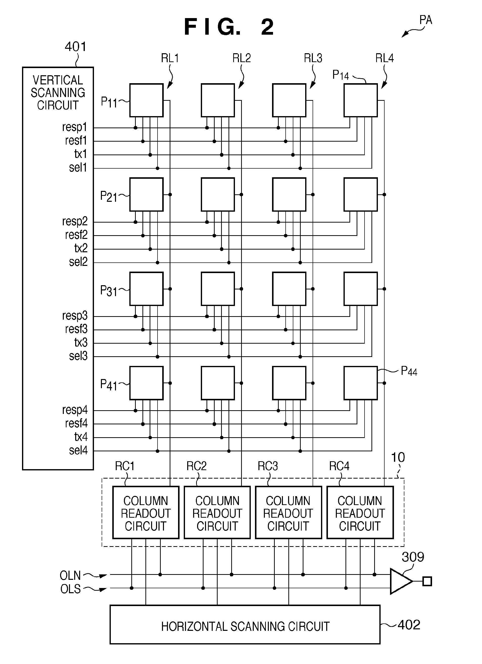
[0159]As shown in FIG. 17, each of pixels P11i to P44i in a pixel array PA of an image sensor 102 does not include the first reset unit 202. FIG. 17 is a circuit diagram of the structure of the pixel P11i in the image sensing apparatus according to the third embodiment of the present invention.

[0160]When resetting a photoelectric conversion unit 201 in the pixel P11i, both signals “tx1” and “resf1” change to an active level at once to turn on both a transfer unit 203 and second reset unit 206. Then, both of remaining charges in the photoelectric conversion unit 201 and remaining charges in the charge-voltage conversion converter 204 are exhausted to the power supply via the transfer unit 203 and second reset unit 206. FIG. 17 is a circuit diagram of the str...

fourth embodiment

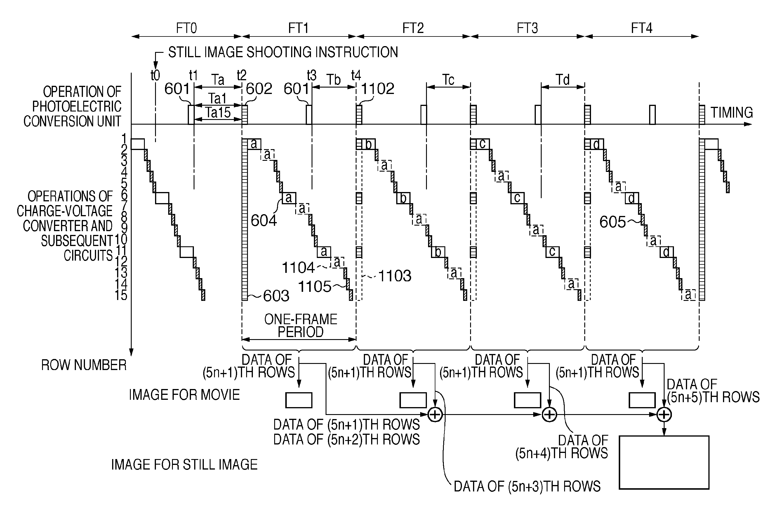
[0219]FIG. 31 schematically shows an operation in the movie shooting mode in the In FIG. 31, the abscissa axis represents the timing. An upper part of the ordinate axis represents the position of a pixel row associated with a signal readout operation from a photoelectric conversion unit 201 up to the memory 2903. A lower part of the ordinate axis represents a signal output operation from the memory 2903.

[0220]As shown in FIG. 31, a first accumulation period group T2a is a group of first accumulation periods T2a1 to T2a15 which partially overlap each other by the same duration between at least two adjacent rows. More specifically, the completion timing of a reset operation 3101 is delayed from that of the reset operation of an immediately preceding row by the timing taken for a first readout operation 3102 of the immediately preceding row. This makes the first accumulation periods T2a1 to T2a15 in the first accumulation period group T2a equal to each other. The delay is a constant t...


PUM


Abstract

An image sensing apparatus comprises: a pixel array; a driving unit; a readout unit which, when performing still image shooting parallel to movie shooting, reads out, in each of successive frame periods, first signals from a first pixel group, and reads out, over the successive frame periods, second signals of a first frame period from pixels of a second pixel group that are different from each other between the successive frame periods; and a generation unit which generates an image signal for a movie of one frame in each of the successive frame periods from the first signals read out in each of the successive frame periods, and also generates an image signal for a still image of one frame in the first frame period by composing the first signals read out in the first frame period and the second signals read out over the successive frame periods.

Description

BACKGROUND OF THE INVENTION[0001]1. Field of the Invention[0002]The present invention relates to an image sensing apparatus.[0003]2. Description of the Related Art[0004]Recent popular image sensing apparatuses such as a digital camera and digital video camera can capture both still images and movies using image sensors such as a CMOS image sensor.[0005]When capturing a movie with an image sensor, the image sensing apparatus requires an electronic shutter function to control the exposure of the image sensor because it is difficult to use a mechanical shutter. The electronic shutter function controls the shutter speed by changing the charge accumulation time of pixels in accordance with the brightness of an object to accumulate a signal at an appropriate level. The electronic shutter function includes a simultaneous electronic shutter function and slit rolling electronic shutter function, as described in Japanese Patent Laid-Open No. 2007-028337.[0006]Some image sensing apparatuses of...

Claims


Application Information

Patent Timeline
Patent Type & Authority Patents(United States)
IPC IPC(8): H04N5/225H04N5/335H04N3/14H04N5/341H04N5/345H04N5/347H04N5/374H04N5/376
CPCH04N5/23232H04N5/23245H04N5/343H04N5/3535H04N23/951H04N23/667H04N25/42H04N25/533
Inventor UCHIDA, MINEO
Owner CANON KK
Why Eureka
Try Eureka