

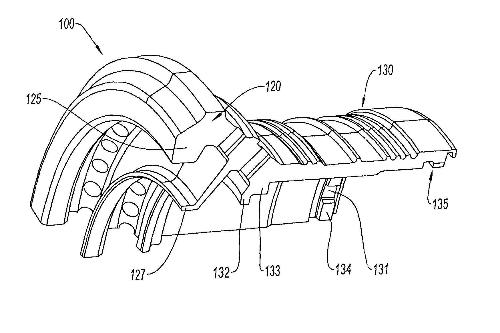
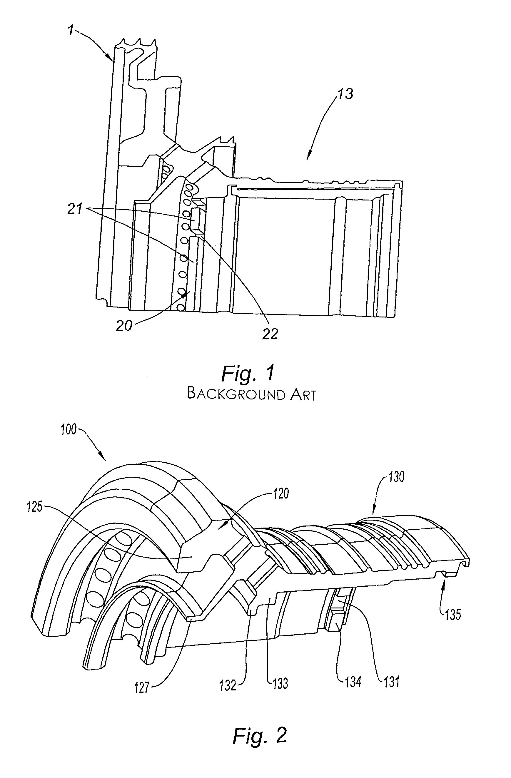
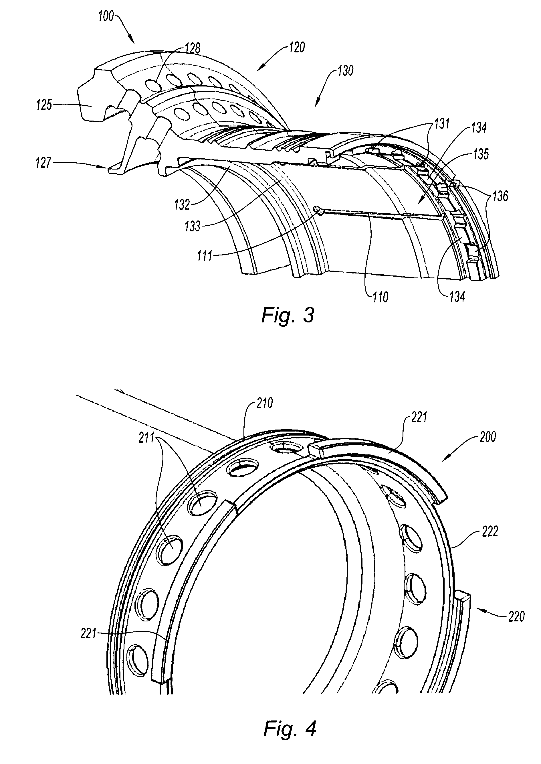
Bearing support journal and assembly of such a journal and a sealing sleeve
a support journal and sealing sleeve technology, applied in the direction of bearing components, gas turbine plants, shafts and bearings, etc., can solve the problems of weakening the journal, high axial stresses on the interior dog coupling of the journal, and fatigue in the journal near the edges, so as to limit the mechanical fatigue introduced and reduce mechanical stresses.
- Summary
- Abstract
- Description
- Claims
- Application Information
AI Technical Summary
Benefits of technology
Problems solved by technology
Method used
Image

Examples
Embodiment Construction
[0074]A twin-spool turbojet engine with a front-mounted fan, for example, comprises a low-pressure spool, known as the LP spool, and a high-pressure spool known as the HP spool.
[0075]The shaft of the LP spool is guided in rotation about the axis of the engine in bearings supported by the fixed structure of the engine whereas the shaft of the HP spool is guided by bearings supported by the LP spool, the shafts of the two spools being concentric.
[0076]The HP turbine disk is secured to a journal for mounting the bearing that allows the HP shaft to rotate with respect to the LP shaft, via which the HP shaft is supported by the LP shaft. The LP shaft is housed in a cylindrical sealing sleeve 200 secured to the journal 100 as depicted in FIG. 25. The bearing comprises an inner ring, secured to the LP shaft, and an outer ring 500 secured to the journal 100.
[0077]Still with reference to FIG. 25, in order to keep the bearing outer ring 500 in position, the sealing sleeve 200, a sealing disk ...
PUM
 Abstract
Description
Claims
Application Information