Conveyor Belt Section

a conveyor belt and section technology, applied in the direction of conveyors, conveyor parts, transportation and packaging, etc., can solve the problems of localised stress and wear, limit the degree,

Active Publication Date: 2014-03-13
FINATZER BARBARA ANNE
View PDF5 Cites 1 Cited by
  • Summary
  • Abstract
  • Description
  • Claims
  • Application Information

AI Technical Summary

Benefits of technology

[0017]Preferably, the base is made from an elastomeric material that is more wear resistant than the elastomeric material forming the side walls.
[0018]Generally, the side walls are made from an elastomeric material that is more resistant to fatigue than the material forming the base.
[0019]Typically, at least two conveyor belt sections are arranged with aligned end sections secured together by a securing means to form a composite conveyor belt.

Problems solved by technology

A drawback of the known belts is that their shape: (i) limits the degree to which they can bend horizontally (i.e. side-to-side) and vertically (i.e. up-and-down); and (ii) causes localised areas of stress and wear.

Method used


Image

  • Conveyor Belt Section
  • Conveyor Belt Section
  • Conveyor Belt Section

Examples


Embodiment Construction

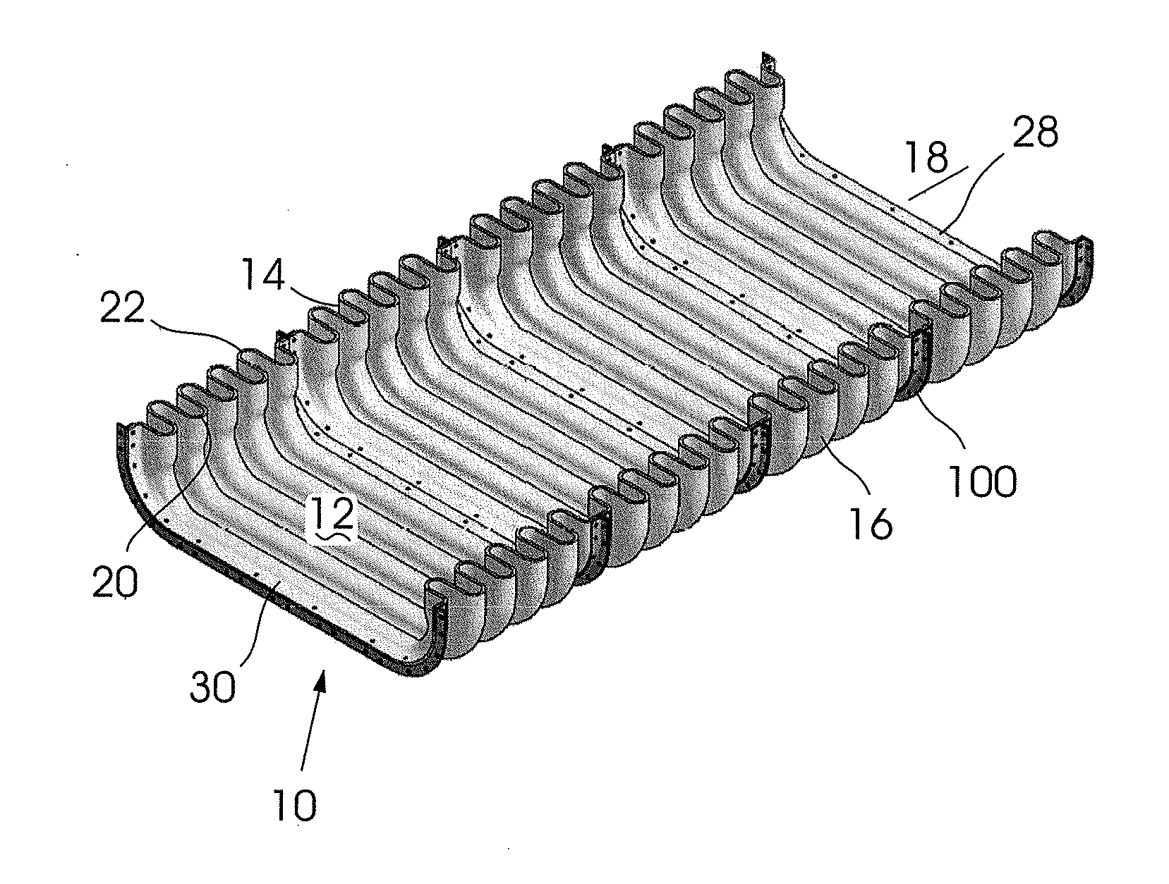
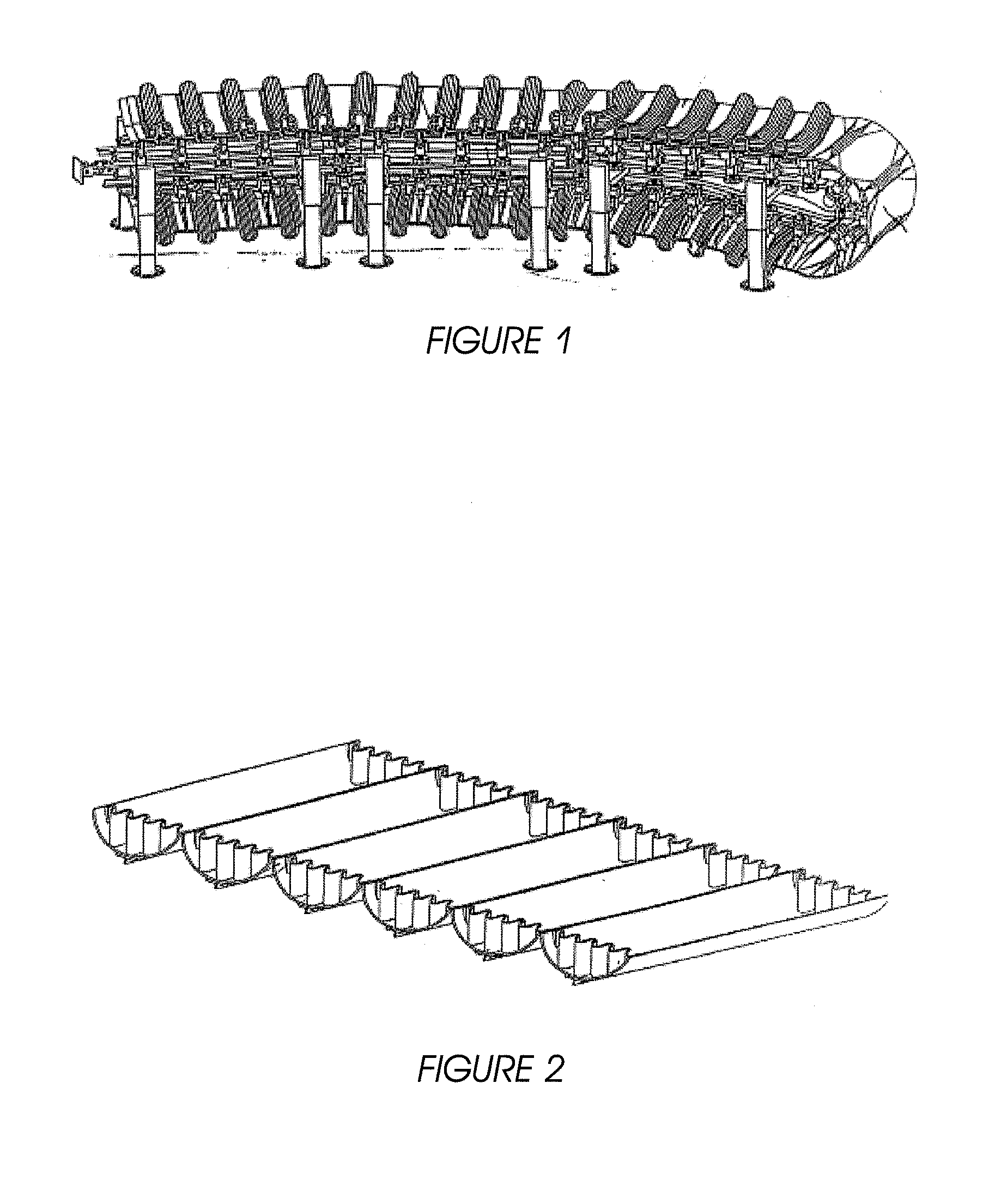
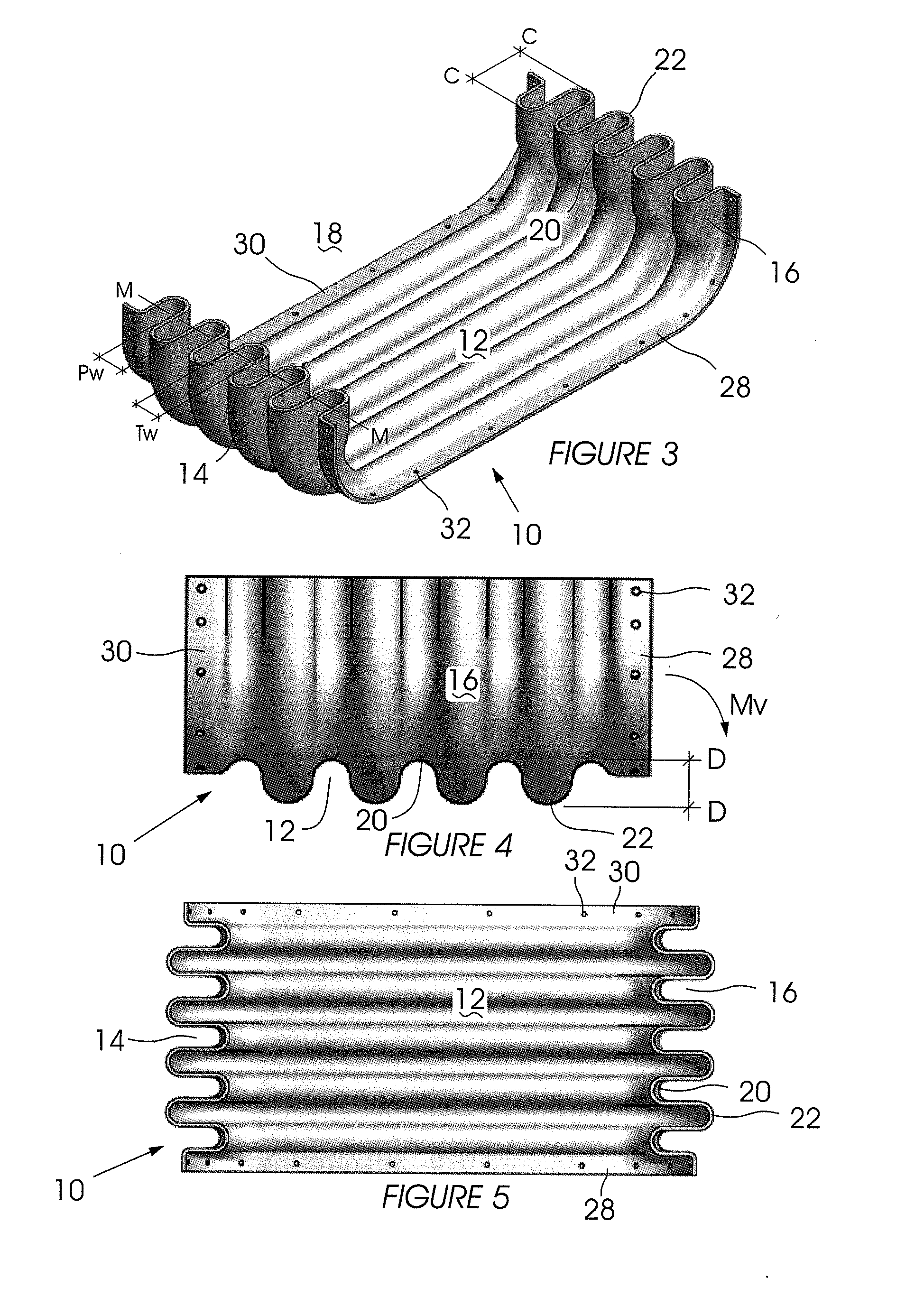
[0036]With reference to FIGS. 3 to 7 of the drawings, a conveyor belt section 10 according to the invention includes a base 12 and side walls 14 and 16 extending angularly upwards from opposing sides of the base to form a channel 18.

[0037]The side walls 14 and 16 retain material transported on the conveyor belt section 10 within the channel 18.

[0038]When in a relaxed state, the conveyor belt section 10 is corrugated, with at least two peaks 20 and two troughs 22 spaced axially and equidistant along the belt section 10 and extending continuously across the side wall 16, base 12 and side wall 14.

[0039]In this specification:[0040](i) Conveyor belt section means a single conveyor belt section that is not joined to any other conveyor belt section.[0041](ii) “spaced equidistant” is intended to mean that the distance between peaks 20 and troughs 22 is constant. The prior art belt in FIG. 1 shows variable frequency between peaks and troughs (assuming that the flat sections are regarded as t...


PUM


Abstract

A conveyor belt section (10) capable of bending vertically and horizontally includes a base (12) and side walls (14, 16) extending anguiarly from opposing sides of the base (12) to form a channel (18), wherein the belt section (10) is corrugated with at least two alternating peaks (20) and troughs (22) extending continuously across the side walls (14, 16) and base (12).

Description

BACKGROUND[0001]The present invention relates to a corrugated conveyor belt section.[0002]Partially corrugated conveyor belts are known. For instance, FIG. 1 (DE10149101) shows a belt made up of belt sections that include: (i) a single fold forming a rib that extends across the width of the belt section; and (ii) planar portions neighbouring the rib. And, FIG. 2 (same patent) shows a belt having a base made up of semi-cylindrical sections and sinusoidal side walls.[0003]A drawback of the known belts is that their shape: (i) limits the degree to which they can bend horizontally (i.e. side-to-side) and vertically (i.e. up-and-down); and (ii) causes localised areas of stress and wear.[0004]The corrugated conveyor belt section according to the current invention aims to address this drawback.SUMMARY OF THE INVENTION[0005]According to a first aspect of the present invention there is provided a conveyor belt section including:[0006]a base;[0007]side walls extending angularly from opposing ...

Claims


Application Information

Patent Timeline
Patent Type & Authority Applications(United States)
IPC IPC(8): B65G15/30
CPCB65G15/30B65G17/02B65G39/20B65G15/42B65G15/40B65G15/10
Inventor FINATZER, KARL HEINZ NIKOLAUS
Owner FINATZER BARBARA ANNE
Why Eureka
Try Eureka