Flexible transfer installation and foodstuff transfer system provided with the flexible transfer installation

a technology of flexible transfer and installation, which is applied in the direction of rolling carts, packaging, storage devices, etc., can solve the problems of increasing the manufacturing and assembly cost difficult to ensure the stability of the transfer conveyer, and generating wear, etc., to achieve compact construction, reduce manufacturing and assembly costs, and high resistance to wear

Inactive Publication Date: 2005-10-13
MAYEKAWA MFG CO LTD
View PDF3 Cites 9 Cited by
  • Summary
  • Abstract
  • Description
  • Claims
  • Application Information

AI Technical Summary

Benefits of technology

[0012] The present invention was made in light of the problems of prior art. The object of the invention is to provide a flexible transfer installation provided with a transfer conveyer which is flexible in the transfer direction, the transfer pieces of the conveyer being able to be piled in a vertical spiral without the occurrence of lateral movement of the transfer pieces in lateral directions perpendicular to the transfer direction, of which the transfer pieces are composed so that the contact portion of the transfer pieces contacting to each other when piled in a vertical spiral is highly resistant to wear, and which is compact in construction and produced with decreased man-hour resulting in decreased manufacturing cost by simplifying the structure of the spacer member of the transfer piece to reduce the processing man-hour of the spacer member; and to provide a foodstuff transfer system provided with the flexible transfer installation.

Problems solved by technology

However, in prior art 1, as the upper end of the outside-part of the spacer member contacts the outwardly inclined face in line contact, there occurs high contact pressure which causes a problem that wear will be generated due to the high contact pressure.
As a result, it is difficult to secure stable operation of the transfer conveyer when the transfer pieces are piled in a spiral.
Still further, in prior art 1, as the spacer member is formed to have an outwardly inclined part at the lower end part of the outside-part thereof and an inwardly inclined part at the lower end of the inside-part thereof, processing man-hour of the spacer member increases and also assembling man-hour increases to engage the upper end of the spacer member with the inclined parts formed in the lower end part of the spacer member right above in the spiral, resulting in an increase manufacturing and assembling cost of the transfer conveyer.
In prior art 1 and 2, as the surface of the connection members of the transfer pieces to form the transfer passage contact the surface of driving members such as a drive roller, drive chain, etc., there may occur a sanitary problem when foodstuff is transferred.
As a result, the driving apparatus for driving the chains becomes complicated resulting in an increased price.
Still further, in prior art 1 and 2, each motor for driving the transfer conveyer is installed vertically, the height of the driving apparatus is increased and its maintainability is not good for the speed change gear drive and motor is installed vertically.
As mentioned above, there are several problems to be solved in the prior arts.

Method used


Image

  • Flexible transfer installation and foodstuff transfer system provided with the flexible transfer installation
  • Flexible transfer installation and foodstuff transfer system provided with the flexible transfer installation
  • Flexible transfer installation and foodstuff transfer system provided with the flexible transfer installation

Examples


first embodiment

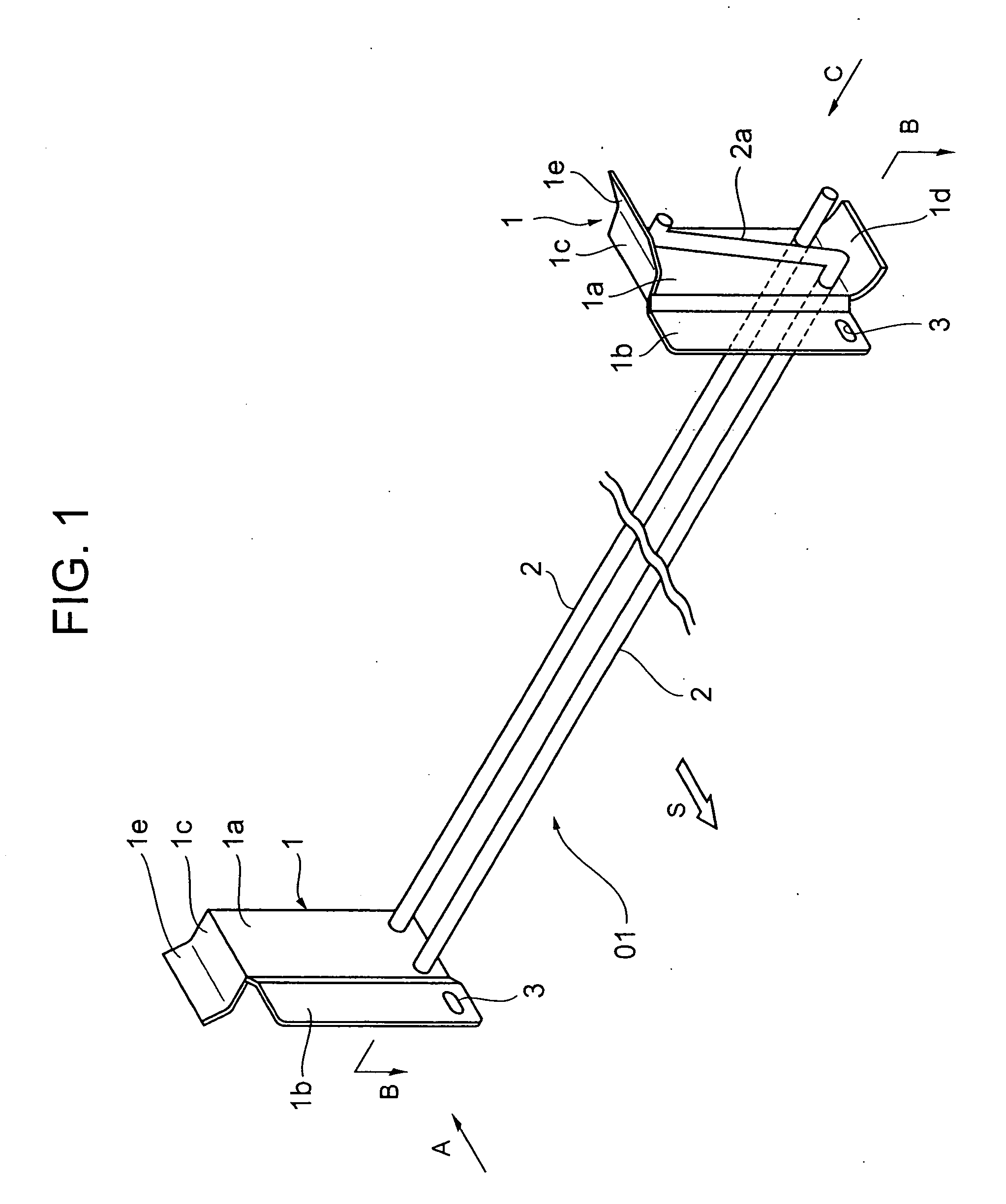
[0096] Referring to FIG. 1-4 showing the detail of the transfer piece 01 composing the transfer conveyer according to the present invention, reference numeral 1 is a spacer member made of plate material. The spacer member 1 is formed to have an inside-part 1b and an outside-part 1a continuing to the inside-part 1b and offsetting from the inside-part 1b outward in lateral direction perpendicular to the transfer direction shown by arrow S in FIG. 1.

[0097] The distance of the offset of the outside-part 1a from the inside-part 1b outward in lateral direction perpendicular to the transfer direction is determined so that the plate thickness of the inside-part 1b is accommodated in the space defined between the inside surface of the outside-part 1b and the extension of the inside surface of the inside-part 1b as shown in FIG. 3.

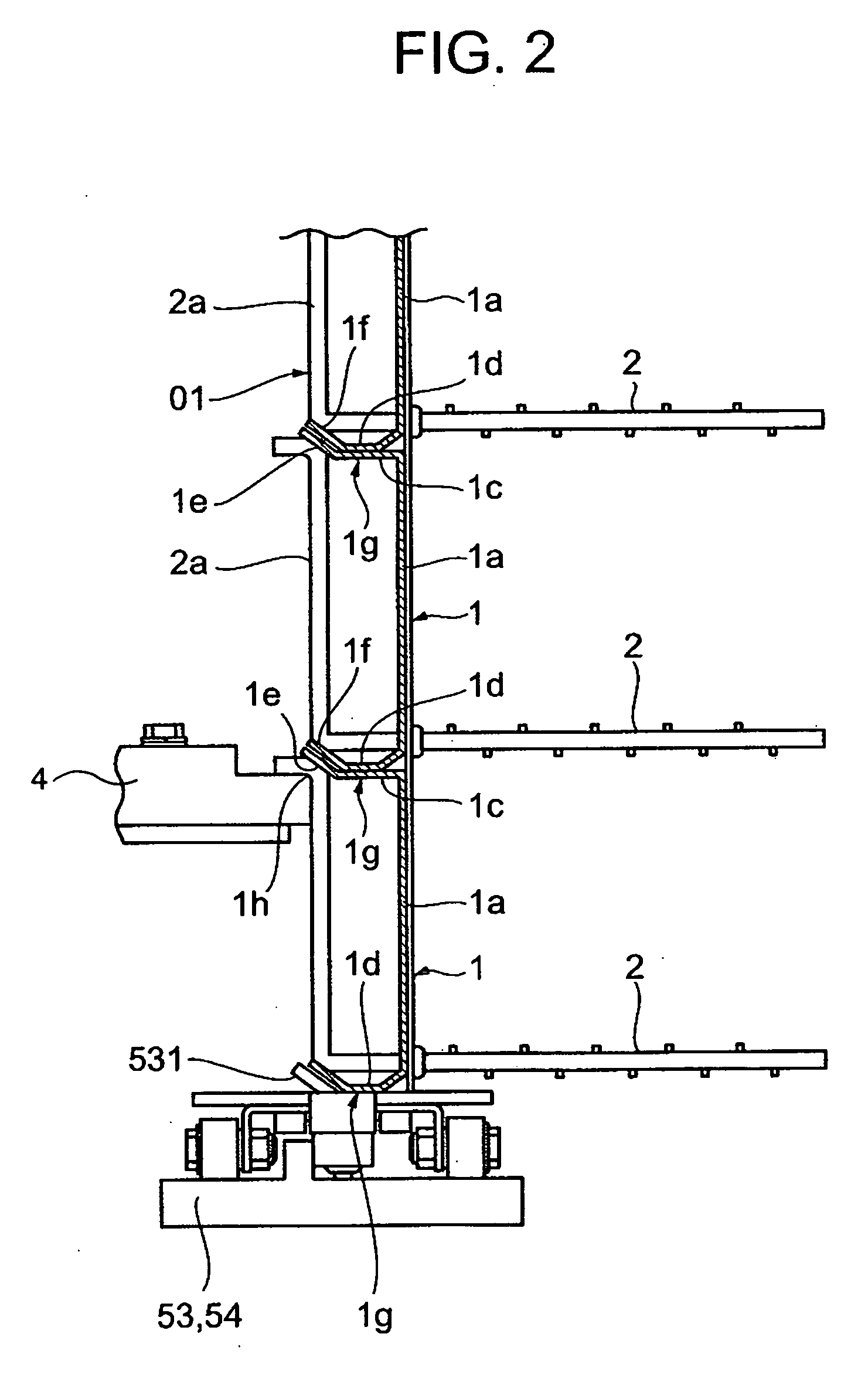
[0098] As shown in FIG. 2, the upper end part and lower end part of the outside-part 1a of the spacer member 1 are formed to have an engaging part 1c and 1d respec...

second embodiment

[0110] Next, referring to FIGS. 5(a), (b), and (c) showing the transfer piece 01, the spacer member 1 is formed to have an outer-side part 1a and an inside-part 1b continuing to the outer-side part 1a and offsetting outward in lateral direction perpendicular to the transfer direction S, an engaging part 1k is formed at the upper or lower end part of the inside-part 1b and outer-side part 1a, the engaging parts bending oppositely to each other in lateral direction perpendicular to the transfer direction, so that the upper part and lower part of the spacer members 1 adjacent to each other in the vertical direction can contact with each other.

[0111] Each engaging part 1k of the inside-part 1b and outer-side part 1a has an inclined face 1m inclined by a certain angle to the vertical plate of the spacer member 1, the lower end part 1i of the vertically adjacent spacer member contacts the inclined face 1m. By this contact, the movement of the vertically adjacent spacer member in lateral d...


PUM


Abstract

The present invention is featured in that a plurality of transfer pieces composing a transfer conveyer are connected to be able to be piled vertically spirally, the transfer pieces having pairs of spacer members each of which is formed to have an inside-part and an outside part continuing to the inside-part and offsetting outward in lateral direction perpendicular to the transfer direction, an engaging part having a contact face extending in the direction parallel to the transfer direction being formed at the upper and lower end part of the outside-part of the spacer member; the transfer pieces can be piled such that vertically adjacent spacer members contact to each other with the contact face of the upper and lower engaging part; an inside chain and an outside chain are provided for allowing the inner side and outer side spacer members to ride on respective chain to advance the transfer conveyer; and the inside chain and outside chain are driven by a single motor.

Description

TECHNICAL FIELD [0001] The present invention relates to a flexible transfer installation applied to a spirally piled endless conveyer, etc. for transferring frozen foodstuff in a refrigeration room, the conveyer being composed of a plurality of transfer pieces connected to be capable of moving relative to each other along the transfer direction, each of the transfer piece being composed of a pair of spacer members and connection members which constitute a transfer passage of frozen foodstuff, etc., the spacer members being fixed to both end sides of the connection members; and to a foodstuff transfer system provided with the flexible foodstuff transfer installation. BACKGROUND ART [0002] Endless transfer conveyers for transferring frozen foodstuff in refrigeration rooms are disclosed in Japanese Patent Pubulication No. 7-100524 (prior art 1), No. 7-25407 (prior art 2), and No. 1-44605 (prior art 3). Each of the conveyers comprises a plurality of transfer pieces connected to be capab...

Claims


Application Information

Patent Timeline
Patent Type & Authority Applications(United States)
IPC IPC(8): B65G17/06B65G17/08B65G21/18
CPCB65G1/0435B65G17/064B65G17/086B65G21/18B65G2207/24
Inventor MIYANISHI, HIDEKISEKINO, AKIRAISHIZAKI, HIDENORI
Owner MAYEKAWA MFG CO LTD
Why Eureka
Try Eureka