Door interlocking system

a technology of interlocking system and door panel, which is applied in the direction of door/window protective device, sliding door/movable grille, shutter/movable grille, etc., can solve the problems of awkward installation and subsequent service adjustment, inconvenience, and inability to adjust the cable system, so as to achieve minimal initial adjustment, easy installation and adjustment, and minimal

Inactive Publication Date: 2007-12-18
PEELLE COMPANY LTD THE
View PDF19 Cites 10 Cited by
  • Summary
  • Abstract
  • Description
  • Claims
  • Application Information

AI Technical Summary

Benefits of technology

[0004]The invention provides a multi-panel motion control system for a freight elevator door landing having a simplified linkage arrangement that is easy to install, requires minimal initial adjustment, and is resistant to wear or other distortion effects that require periodic adjustment or replacement. The linkage of the invention is adapted to be mounted at mid-height on the door panels so that it can be easily installed and adjusted by a technician conveniently working on the level of the respective landing.
[0005]Preferably, the linkage is in a multiple scissors or X-like configuration so that the forces on individual links and pivot connections or pins are balanced and relatively low forces are imposed on the linkage. Consequently, the linkage has the potential of operating over an extended service life with a minimum of wear, and thereby reduces the need for periodic service adjustment or replacement. Mounting brackets for the linkage can be directly secured to the panels and minimum initial adjustment is required. While a pinching hazard at the linkage is remote because in operation the linkage is ordinarily shielded by the elevator car door, the mechanism can include shields to minimize the risk of personal injury or mechanical damage when the linkage is exposed during periodic inspection or maintenance.

Problems solved by technology

Conventional cable systems are prone to go out of adjustment due to permanent stretching of the cables and / or wear of related parts.
Generally, the cable systems are disposed above the door panels thereby making their original installation as well as subsequent service adjustments awkward, tedious and time-consuming.

Method used


Image

  • Door interlocking system
  • Door interlocking system
  • Door interlocking system

Examples


Embodiment Construction

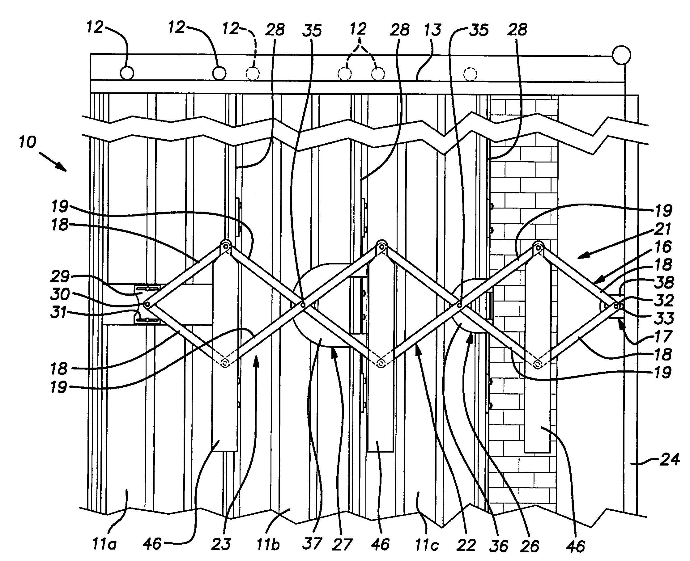
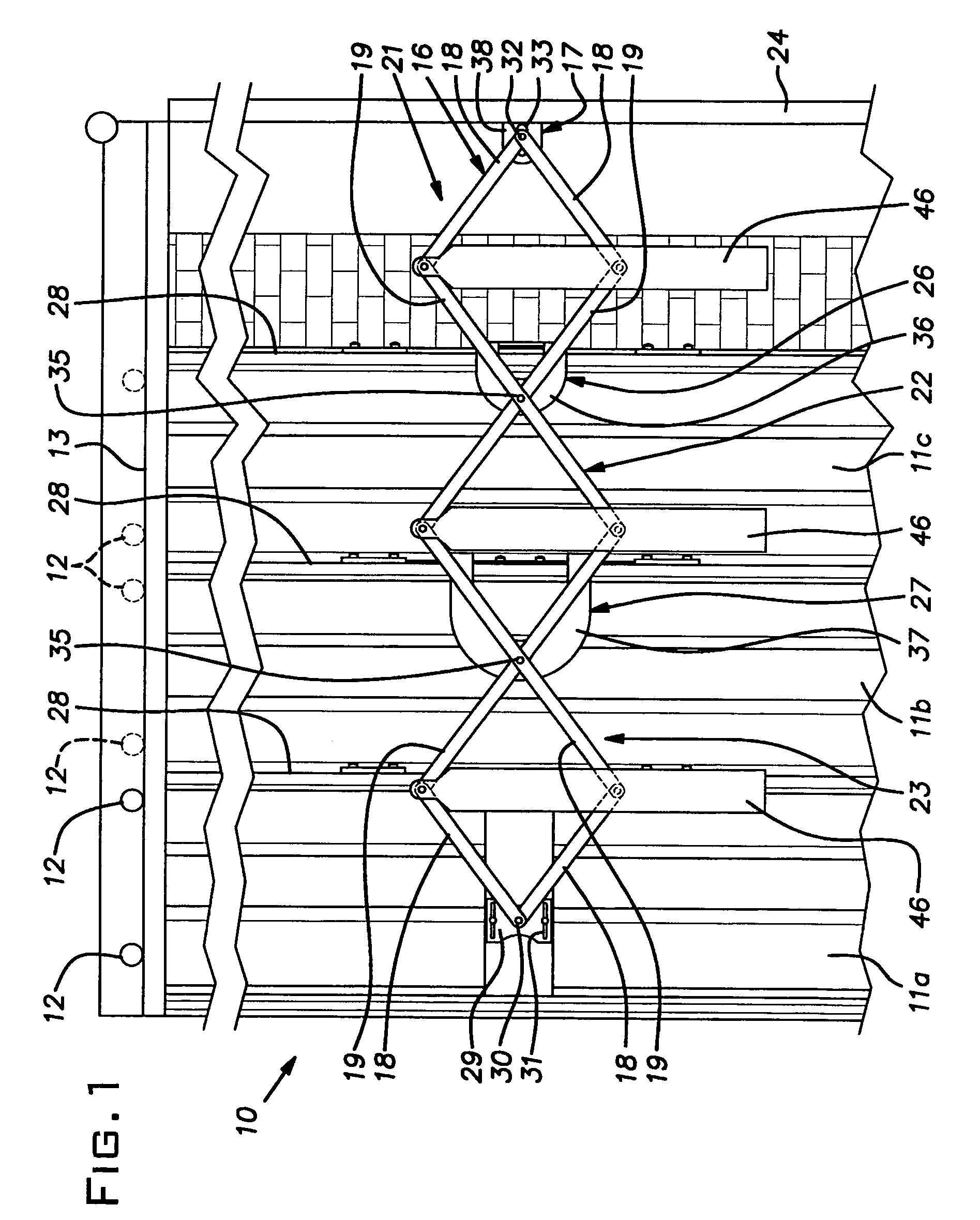
[0010]An assembly 10 of horizontal sliding door panels 11a-11c, is illustrated in the figures. The panels 11, for example, represent the right side of a six-panel door assembly. The left side of the assembly is symmetrical with and a mirror image of FIGS. 1 and 2. The panels 11 are supported on traction rollers 12 supported on overhead tracks 13 in a generally conventional manner.

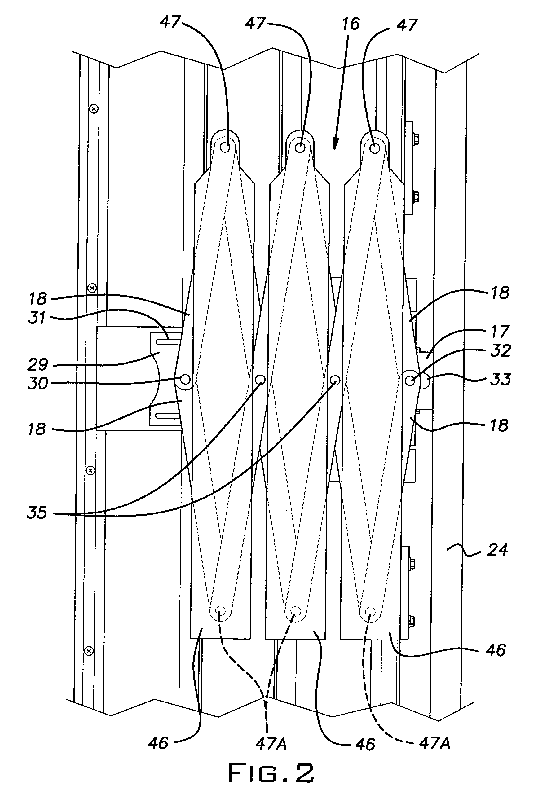
[0011]The door panel assembly 10, as is typical, exists to close the shaft opening at a respective landing when an elevator car is elsewhere and opens for ingress and egress to the car when the car is present at the landing. The panels 11, as seen most clearly in FIGS. 3 and 4, are horizontally spaced or in staggered vertical planes so that they are able to register one behind the other as shown in FIG. 4 when in the open position.

[0012]When the panels 11 move between their respective open and closed positions, it is desirable that they all depart from and arrive at these positions at the same time. It foll...


PUM


Abstract

A door panel position control mechanism for a multiple panel horizontal sliding door assembly of a freight elevator landing. The mechanism comprises a multiple node scissors linkage that is configured to be easily installed and initially adjusted and which has its parts symmetrically balanced about a vertical plane such that excessive eccentric loading on the components is reduced and a long service life is obtained with reduced wear and a reduced need for periodic adjustment.

Description

BACKGROUND OF THE INVENTION[0001]The invention relates to improvements in elevator landing door assemblies and, more particularly, to a position control mechanism for multiple horizontal sliding door panels.PRIOR ART[0002]Freight elevator landing doors of the multiple panel, horizontal sliding type typically have a device to produce simultaneous movement of the panels. A common type of control device uses a cable and pulley system to produce the desired movement rate and distance which, as between the panels are-typically different but proportional.[0003]Conventional cable systems are prone to go out of adjustment due to permanent stretching of the cables and / or wear of related parts. Generally, the cable systems are disposed above the door panels thereby making their original installation as well as subsequent service adjustments awkward, tedious and time-consuming.SUMMARY OF THE INVENTION[0004]The invention provides a multi-panel motion control system for a freight elevator door l...

Claims


Application Information

Patent Timeline
Patent Type & Authority Patents(United States)
IPC IPC(8): B66B13/06A47H5/00B66B13/12E05F11/44
CPCB66B13/06E02B3/14
Inventor DZIWAK, ZYGMUNT
Owner PEELLE COMPANY LTD THE
Why Eureka
Try Eureka