Headbox for a machine for producing a fibrous web

a technology of fibrous web and headbox, which is applied in the direction of machine wet end, textiles and papermaking, papermaking, etc., can solve the problems of high production cost, unstable operation, and known perforated distribution pipe pla

Inactive Publication Date: 2012-11-06
VOITH PATENT GMBH
View PDF6 Cites 0 Cited by
  • Summary
  • Abstract
  • Description
  • Claims
  • Application Information

AI Technical Summary

Benefits of technology

[0014]The headbox according to the present invention permits the construction and operation of a compact headbox with a clearly reduced pressure loss in the area of the perforated distributor pipe plate in contrast to the current state of the art so that it provides a process which is technologically sufficient and operationally stable headbox even over an expanded operational area. In addition the inflowing speed of the fibrous stock suspension into the intermediate channel of the headbox is reduced in a desirable way by at least one diffuser. Also, in order to be able to design the perforated distributor pipe plate with a shorter length at a lower pressure loss, the partition area must be small in order to control the diversion effects as well as the hydraulic function of a diffuser in a flow cross section at a short length. The length of the perforated distributor pipe plate however continues to represent a sufficient “guide length”, so that undesirable cross components to the machine direction can be completely avoided in the fibrous stock suspension emerging from the perforated distribution pipe plate.
[0016]In a first embodiment of the headbox of the present invention, the partition area of the perforated distributor pipe plate assumes a value in the range of ≦4,000 square millimeters (mm2), for example ≦2,500 mm2, or 200 to 1,000 mm2. These value ranges contribute substantially, to a compact construction of the headbox.
[0017]Moreover, the perforated distributor pipe plate may have an open area of ≧30%, for example ≧40%, or ≧50%, whereby the open area of the perforated distributor pipe plate is the ratio of the total downstream total area of the channels of the perforated distributor pipe plate arranged in rows and columns and the downstream total area of the perforated distributor pipe plate. These value ranges provide the advantage of a slow inflow of the fibrous stock suspension into the intermediate channel. The desired volume flow constancy should flow at an as low a flow dynamic as possible into the intermediate channel, or respectively onto the apparatuses for dosing of fluid and to thereby keep the transition from dynamic into pressure as low as possible. The fibrous stock suspension flow is as “filled” as possible—in other words with the largest possible channels—through the perforated distributor pipe plate.
[0018]The individual channel of the perforated distributor pipe plate may have a round channel cross section with a predefined channel diameter. The middle channel diameter of the individual channel of the perforated distributor pipe plate and the length of the perforated distributor pipe plate are, for example, at a ratio of 1:2 to 1:10, 1:3 to 1:8, or 1:4 to 1:5. These value ranges provide improved operating stability of the headbox in a possibly expanded operational window.
[0019]The diffuser formed in the individual channel of the perforated distributor pipe plate can have at least one rapid expansion, for example a step expansion and / or at least in some areas a continuous expansion, for example a cone having a cone angle of ≦30°. Also the diffuser formed in the individual channel of the perforated distributor pipe plate may have at least two of the previously described expansions. These designs contribute substantially to the desired or respectively necessary low inflow speed of the fibrous suspension into the intermediate channel of the headbox and to an advantageous pressure recovery.
[0025]The inventive headbox is extremely well suited for utilization in a machine for the production of a fibrous web, especially a paper or cardboard web. The fibrous web produced in the machine with at least one inventive headbox possesses outstanding properties throughout, since among other advantages, control of its fiber orientation cross profile, as well as its base weight cross profile, is possible.

Problems solved by technology

Due to relatively strong fluid frictions, great flow speeds and similar conditions, these long lengths cause large pressure losses in the fibrous stock suspension which are disadvantageous for the operating stability and the desired compact construction of a respective headbox.
In addition, the known perforated distribution pipe plates, whether they are in the embodiment of perforated plates or tube banks, are very cost intensive in their production.

Method used


Image

  • Headbox for a machine for producing a fibrous web
  • Headbox for a machine for producing a fibrous web
  • Headbox for a machine for producing a fibrous web

Examples


Embodiment Construction

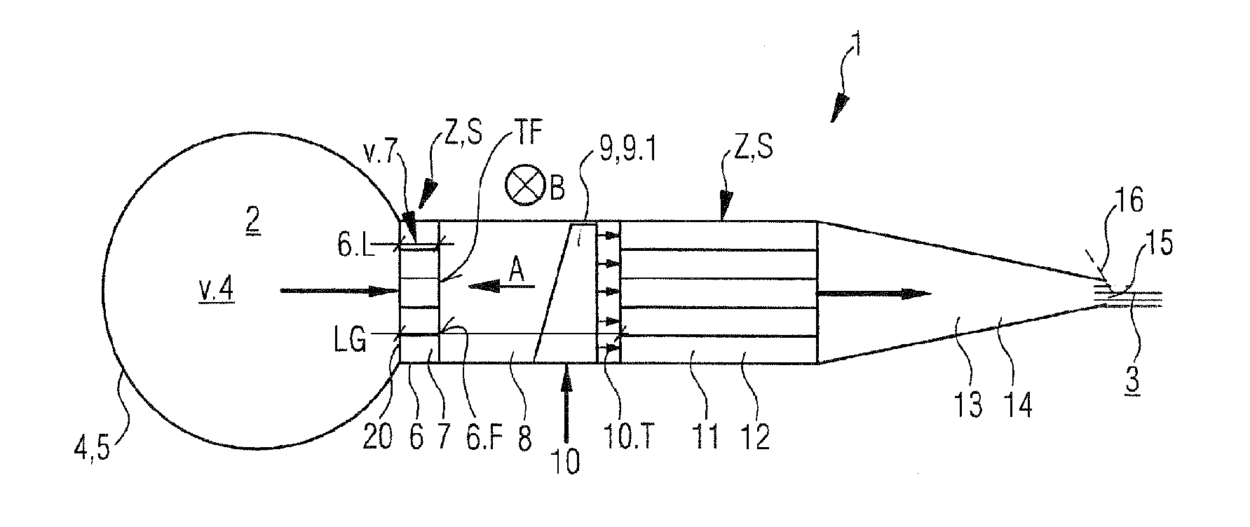
[0032]Referring now to the drawings, and more particularly to FIG. 1, there is shown a vertical longitudinal sectional view of an exemplary embodiment of headbox 1 for a machine for producing fibrous web 3 from fibrous stock suspension 2. Illustrated headbox 1 can also be designed as, a multi-layer headbox utilizing at least two different fibrous stock suspensions to produce fibrous web 3. Fibrous web 3 can be a paper, cardboard or tissue web.

[0033]Headbox 1 includes one feed device 4 in the embodiment, for example, of cross distribution pipe 5, or a circular distributor (not illustrated here) with a multitude of tubes, feeding one fibrous stock suspension 2.

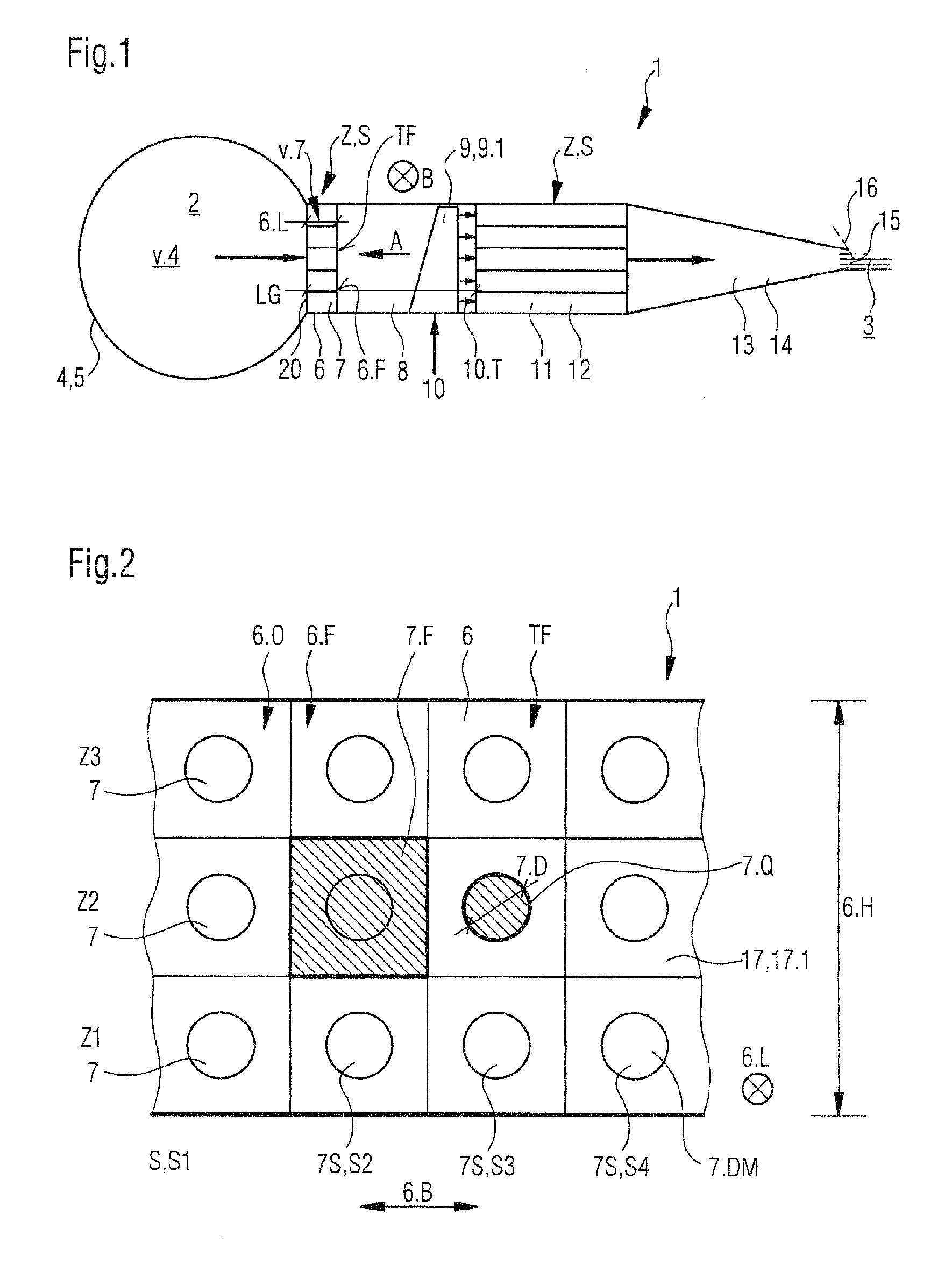
[0034]Perforated distribution pipe plate 6, which is equipped with a plurality of channels 7 which are arranged in rows Z and columns S, is located downstream adjacent to feed device 4 (compare FIG. 2). Again located adjacent downstream from perforated distribution pipe plate 6 is intermediate channel 8, extending across width B...


PUM


Abstract

A headbox includes a feed device for feeding at least one fiber suspension, a perforated distribution pipe plate arranged immediately downstream thereof and having a plurality of channels arranged in lines and columns and an intermediate channel arranged downstream thereof extending over the width of the headbox and having a plurality of apparatuses for dosing a fluid in partial fluid streams to the at least one fiber suspension in an adjustable / controlled manner. The apparatuses are spaced apart from each other in the width direction of the headbox and the individual apparatuses include a plurality of dosing channels having respective dosing channel openings on the outlet side and a dosing channel length, arriving at different levels and being connected to a common supply channel. The headbox further includes a downstream turbulence generator having a plurality of flow channels arranged in lines and columns and a headbox nozzle which is directly contiguous to the turbulence generator and which has a nozzle gap. At least some sections of the channels of the perforated distribution pipe plate have a diffuser and the perforated distribution pipe plate has a length which is ≧0.5·√{square root over (partition)} area the partition area being the surface of the downstream perforated distribution pipe plate divided by the total number of the channels of the perforated distribution pipe plate.

Description

CROSS REFERENCE TO RELATED APPLICATIONS[0001]This is a continuation of PCT application No. PCT / EP2009 / 063836, entitled “HEADBOX FOR A MACHINE FOR PRODUCING A FIBROUS WEB”, filed Oct. 22, 2009, which is incorporated herein by reference.BACKGROUND OF THE INVENTION[0002]1. Field of the Invention[0003]The present invention relates to a headbox for a machine or producing a fibrous web, in particular a paper or cardboard web, from at least one fibrous stock suspension.[0004]2. Description of the Related Art[0005]German disclosure document DE 44 16 898 A1 describes a headbox for a paper machine including a feed device for a stock suspension comprising a guiding element with a plurality of channels; upstream from the guiding element is a mixing chamber with several infeed devices which are distributed over the headbox for a fluid which is to be added to the stock suspension and which differs in its characteristics from the stock suspension; and a nozzle chamber forming an outlet opening for...

Claims


Application Information

Patent Timeline
Patent Type & Authority Patents(United States)
IPC IPC(8): D21F1/18
CPCD21F1/02D21F1/022
Inventor RUF, WOLFGANGFENKL, KONSTANTINHAUSSLER, MARKUS
Owner VOITH PATENT GMBH
Why Eureka
Try Eureka