Panel positioning mechanism and display device with different positioning modes

a positioning mechanism and positioning mode technology, applied in the direction of instruments, machine supports, electric apparatus casings/cabinets/drawers, etc., can solve the problems of unsuitable popular application, spindle pivoting mechanism manufacturing cost, delay in pivoting mechanism, etc., and achieve the effect of low cos

Active Publication Date: 2012-11-13
WISTRON CORP
View PDF10 Cites 6 Cited by
  • Summary
  • Abstract
  • Description
  • Claims
  • Application Information

AI Technical Summary

Benefits of technology

[0015]According to the claimed invention, the contacting portion of the present invention can slide inside the slot, and positions of the contacting portion relative to the slot can be adjusted by pressing the releasing component for adjusting elevation of the panel of the displaying device, so as to adjust the view angle of the panel according to actual demand and to fold the displaying device by rotating the frame close to the base. In addition, the present invention utilizes the fixing component set to lock the supporting component, the holding component, and the rotational spring set. The fixing component set not only has low cost, but also can provide the strong torque with the rotational spring set for preventing the panel positioning mechanism from idle running.

Problems solved by technology

Generally, movement between a driving component and a passive component of the spindle pivoting mechanism delay easily, so that the spindle pivoting mechanism idles running.
The manufacturing cost of the spindle pivoting mechanism is expensive and is unsuitable for popular application.
The locking pivoting mechanism is more expensive than the spindle pivoting mechanism, and is unsuitable to be a consumer electronic product.
Thus, design of an innovating pivoting mechanism of mixing advantages of the above-said pivoting mechanisms is an important issue of the mechanism industry.

Method used


Image

  • Panel positioning mechanism and display device with different positioning modes
  • Panel positioning mechanism and display device with different positioning modes
  • Panel positioning mechanism and display device with different positioning modes

Examples


Embodiment Construction

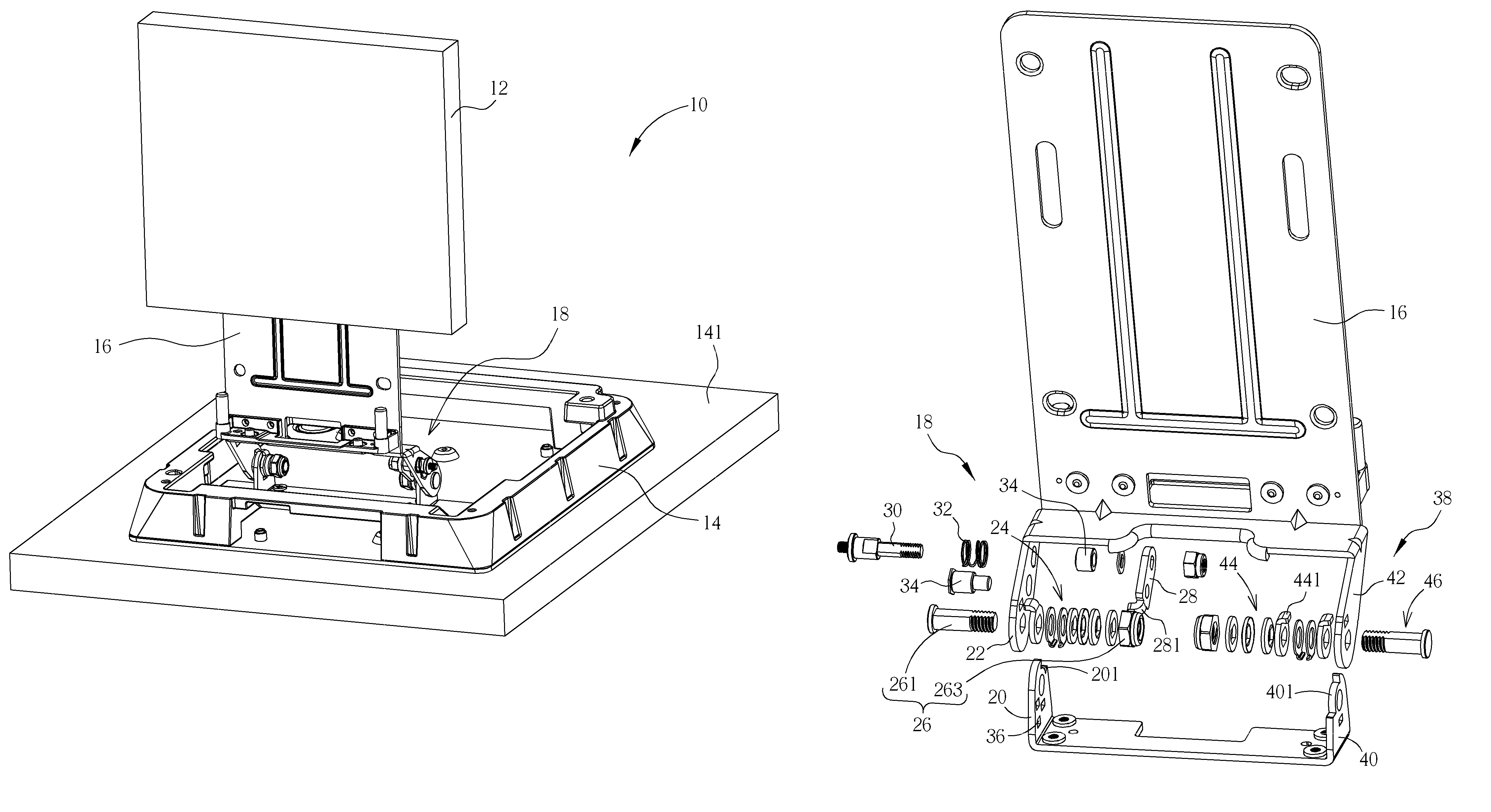
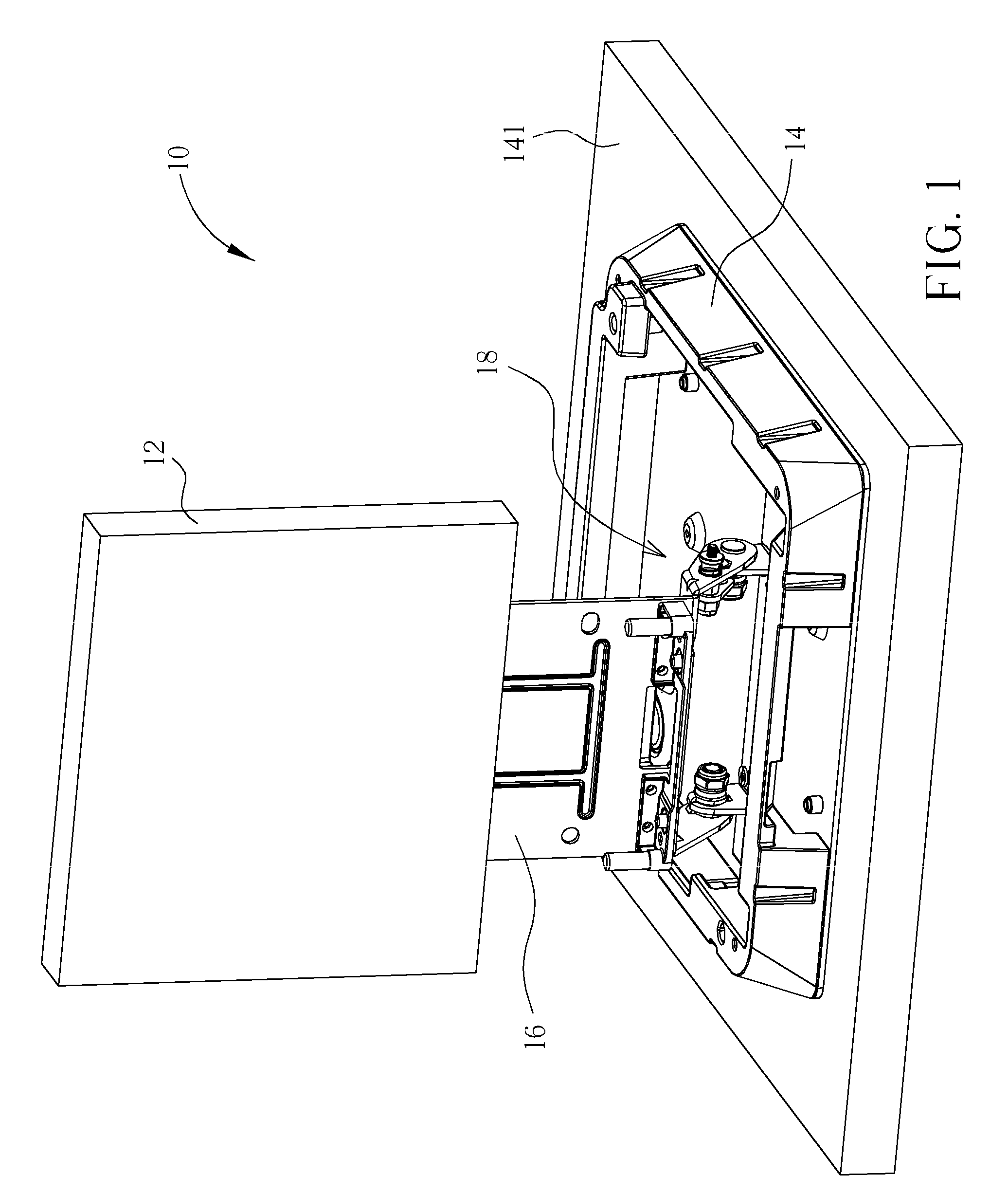
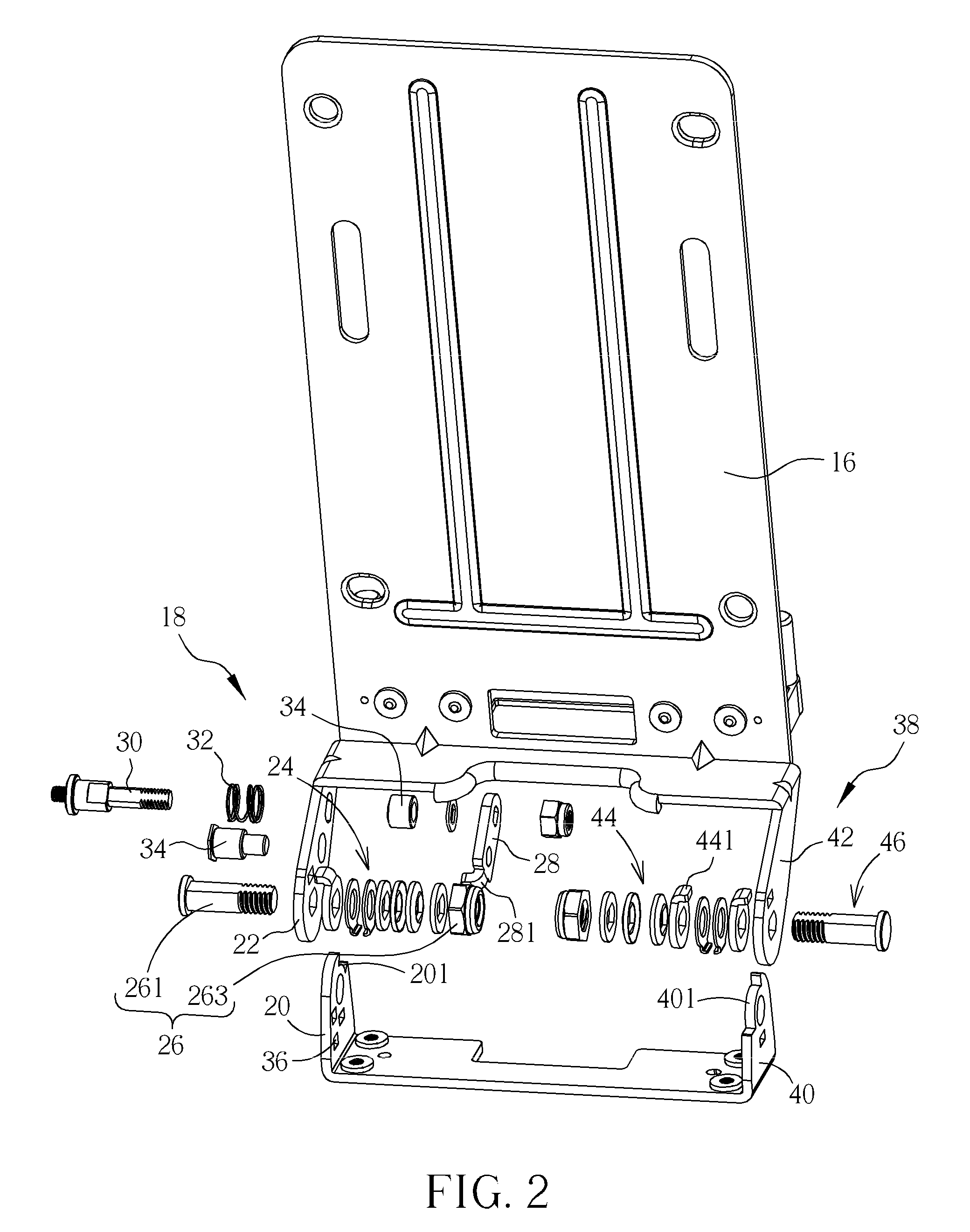
[0021]Please refer to FIG. 1. FIG. 1 is an assembly diagram of a displaying device 10 according to a preferred embodiment of the present invention. The displaying device 10 includes a panel positioning mechanism with different modes. The displaying device 10 can be a liquid crystal display, an all in one PC, and so on. The displaying device 10 includes a panel 12, such as a tablet computer, a base 14 for supporting the panel 12 on a loading plane 141, and a frame 16 connected to the panel 12 for holding the panel 12. As shown in FIG. 1, an angle is formed between the frame 16 and the base 14, so that the panel 12 of the displaying device 10 can be set at a preferable view angle. The displaying device 10 further includes a panel positioning mechanism 18 disposed between the base 14 and the frame 16 for positioning the frame 16 relative to the base 14, meanwhile positioning an angle between the panel 12 and the loading plane 141, so as to adjust the view angle of the panel 12 accordin...


PUM


Abstract

A panel positioning mechanism includes a supporting component, and a slot is formed on a side of the supporting component. The panel positioning mechanism further includes a loading component disposed on a side of the supporting component, a rotational spring set connected to the supporting component and the loading component, a fixing component set for fixing the supporting component, the loading component, and the rotational spring set, a contacting component connected to the loading component and disposed inside the slot in a slidable manner so as to constrain rotation of the loading component within a first range, and a releasing component passing through the loading component and fixed on the contacting component for driving a contacting portion of the contacting component to separate from the slot on the supporting component, so that the loading component can rotate outside the first range.

Description

BACKGROUND OF THE INVENTION[0001]1. Field of the Invention[0002]The present invention relates to a panel positioning mechanism, and more particularly, to a panel positioning mechanism with different positioning modes and a displaying device therewith.[0003]2. Description of the Prior Art[0004]The pivoting mechanism of a common electronic device, such as a supporting module of a notebook computer or a tablet computer, may be of many types, like a continuous pivoting mechanism, a locking pivoting mechanism, and a spindle pivoting mechanism, disposed between an upper casing and a lower casing for adjusting a view angle of the upper casing relative to the lower casing. Generally, movement between a driving component and a passive component of the spindle pivoting mechanism delay easily, so that the spindle pivoting mechanism idles running. The manufacturing cost of the spindle pivoting mechanism is expensive and is unsuitable for popular application. The locking pivoting mechanism merel...

Claims


Application Information

Patent Timeline
Patent Type & Authority Patents(United States)
IPC IPC(8): F16M11/00
CPCF16M11/10F16M13/00F16M2200/022
Inventor CHEN, TA-WEIHSIEH, CHIA-HSIN
Owner WISTRON CORP
Why Eureka
Try Eureka