Microscopy system for eye surgery

a microscopy system and eye surgery technology, applied in the field of eye surgery microscopy systems, can solve the problems of disturbing vibration, difficult alignment of the toric intraocular lens, and inability to completely prevent the mechanical vibration of the eye surgery microscopy system, etc., and achieve the effect of shortening the computation tim

Active Publication Date: 2012-11-13
CARL ZEISS MEDITEC AG
View PDF41 Cites 6 Cited by
  • Summary
  • Abstract
  • Description
  • Claims
  • Application Information

AI Technical Summary

Benefits of technology

[0021]An image processing in as short a computation time as possible is required in order to make possible a real time display of images of the patient eye. For shortening the computation time, the center of the circular structure and/or the angular position of the at least one marking is tracked by means of

Problems solved by technology

On the other hand, mechanical vibrations of eye surgery microscopy systems cannot be completely prevented.
These vibrations become disturbingly noticeable during the imaging of an object region and primaril

Method used


Image

  • Microscopy system for eye surgery
  • Microscopy system for eye surgery
  • Microscopy system for eye surgery

Examples


Embodiment Construction

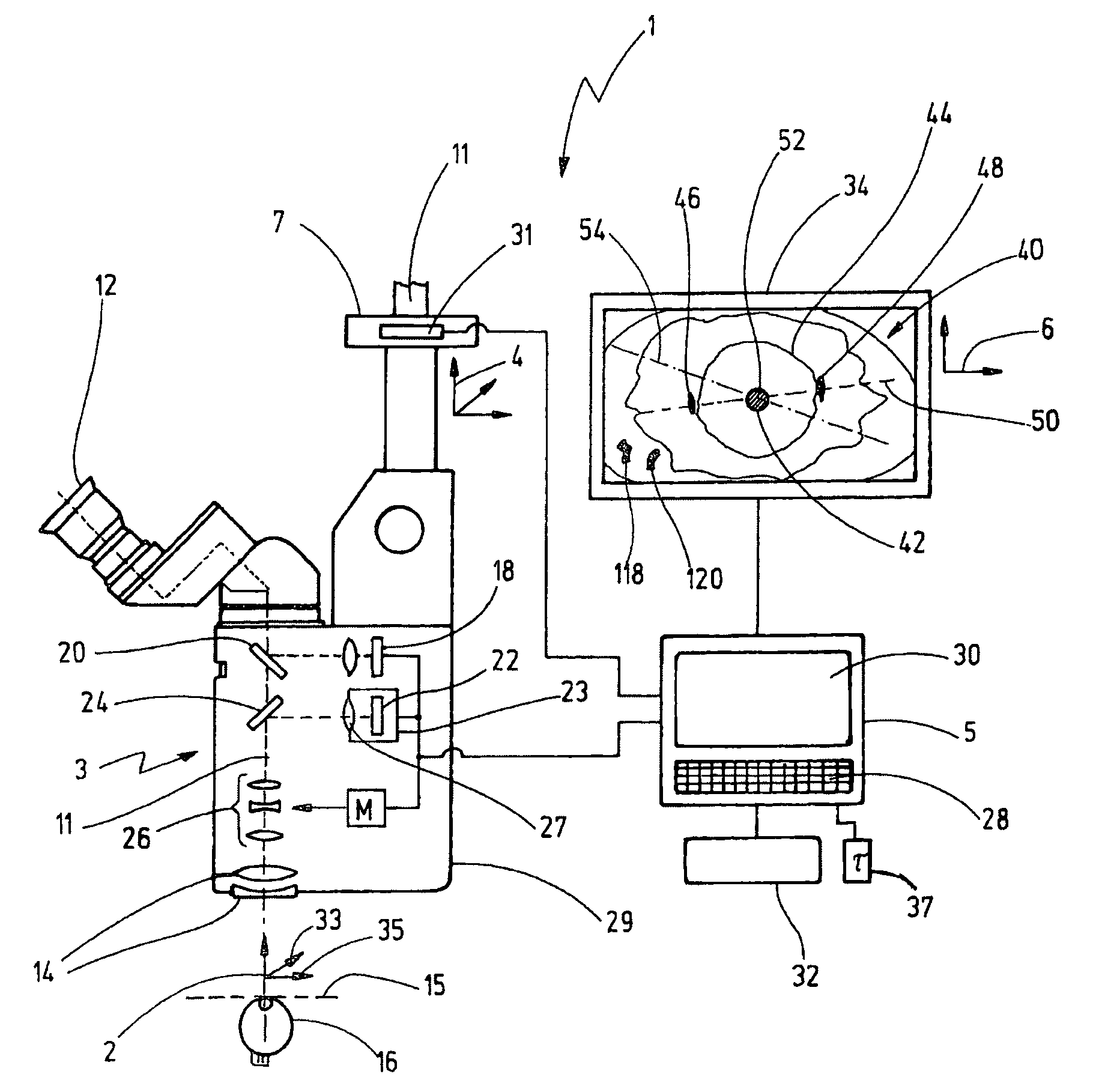
[0049]The eye surgery microscopy system 1 of FIG. 1 includes a surgical microscope 3 having a computer unit 5. The surgical microscope 3 has a surgical microscope base body 29. The surgical microscope 3 is accommodated with an XY-adjusting unit 7 on the arm 9 of a stand not shown further. A suitable XY-adjusting unit is, for example, described in DE 198 56 696 A1. The surgical microscope 3 permits a viewing person to view a patient eye 16 with magnification in an object plane 15 via a binocular viewing beam path 11 through a binocular viewer 12 and an imaging optic having a microscope main objective 14. The surgical microscope 3 has a unit for reflecting in data with a display 18 and a beam splitter 20. Further, a video camera 23 is integrated into the surgical microscope 3 and has a CCD-component as an image sensor 22. The CCD-component has light-sensitive pixels whose edge lengths are approximately 0.03 mm. The object image is supplied to the image sensor 22 via a beam splitter 24...


PUM


Abstract

The invention relates to an eye surgery microscopy system (1) having an imaging optic (14, 11) for the generation of the image of an object plane (15) and having an electronic image sensor (22), which detects the image of the object plane (15) and is connected to a computer unit (5) for the computation of the position of the center of a circular structure (44) of a patient eye (16). The computer unit (5) is designed for the computation of the position of a patient eye (16) outside of the center (52) of the circular structure (44) and provided with at least one marking (46, 48). The computer unit (5) determines the position of the at least one marking (46, 48) with reference to the computed center (52) by means of image processing via correlation with a comparison information, and an angular position of the at least one marking (46, 48) with reference to the computed center (52) by means of image processing.

Description

CROSS REFERENCE TO RELATED APPLICATIONS[0001]This application is a continuation-in-part application of U.S. patent application Ser. No. 12 / 801,689, filed Jun. 21, 2010, publication 2011 / 0019150 A1, published Jan. 27, 2011, and claims priority of U.S. provisional application Ser. No. 61 / 213,608, filed Jun. 24, 2009, and the entire contents of both of the above applications are incorporated herein by reference.FIELD OF THE INVENTION[0002]The invention relates to an eye surgery microscopy system having an imaging optic for generating the image of an object plane and having an electronic image sensor detecting the image of the object plane. The sensor is connected to a computer unit for computing the position of the center of the circular structure of a patient eye.BACKGROUND OF THE INVENTION[0003]An eye surgery microscopy system is required for cataract surgery. The eye surgery microscopy system is used here for magnifying visualization of the surgical region. During the cataract surge...

Claims


Application Information

Patent Timeline
IPC IPC(8): A61B3/14A61B3/00
CPCA61B3/111A61B3/13G06T7/0042G02B21/0012G06T2207/10056G06T2207/30041G06T7/73
Inventor SCHUHRKE, THOMASMECKES, GUNTERGRABER, STEFANTHORNTON, KEITH
Owner CARL ZEISS MEDITEC AG
Why Eureka
Try Eureka