Rear-view mirror system with display device

a rear-view mirror and display device technology, applied in the direction of mirrors, instruments, mountings, etc., can solve the problems of increasing increasing the consumption current, etc., so as to reduce the amount of heat generation, enhance the rearward view, and suppress the effect of current consumption

Inactive Publication Date: 2012-11-13
HONDA LOCK MFG CO LTD
View PDF6 Cites 2 Cited by
  • Summary
  • Abstract
  • Description
  • Claims
  • Application Information

AI Technical Summary

Benefits of technology

[0007]The present invention has been achieved in view of the foregoing situations and it intends to provide a rear-view mirror system with display device capable of using an emission display device at low luminance while sufficiently securing a rearward view by a rear-view mirror and, in addition, capable of obtaining emission information on a display window while decreasing feeling of distance with respect to images reflected on the rear-view mirror.
[0013]In the invention, since the display window of the display device is disposed at the periphery of the rear-view mirror, the rearward view obtained by the rear-view mirror is not narrowed and the visibility for the rearward view can be enhanced. Further, since the emission display information does not transmit the reflection film of the rear-view mirror, and the emission display device and the light reflection device are arranged in the display housing, they do not suffer from the effect of an ambient light. Since the emission display device of high luminance is not necessary, current consumption can be decreased and the amount of heat generation can be suppressed for the emission display device. In addition, since the emission display device and the light reflection device are disposed in the display housing, visibility at the display window can be improved not suffering from the effect from the external light. Further, since the emission display information displayed by the emission display device and reflected on the light reflection device transmits the display window, the difference of focal points between the images behind the car reflected on the rear-view mirror and the emission display information obtained at the display window can be decreased to enhance the visibility.
[0014]Further, in the embodiment of the invention, since the light permeable cover member closing the display window is attached to the display housing so as to make an angle relative to the outer surface of the rear-view mirror, images behind the car due to surface reflection identical with that of the images reflected on the rear-view mirror are not reflected and the visibility can be enhanced, for example, by disposing the cover member directing to the ceiling portion in the car room such that images or light behind the car cannot be reflected on the cover member.
[0015]In another embodiment of the invention, since the display housing is disposed in contiguous with the mirror housing that is swivelably supported by the housing support portion on the side of the car body at a position close to the housing support portion, this can prevent undesired tilting of the mirror housing due to exertion of the weight of the display device on the mirror housing.
[0016]In the further embodiment of the invention, when the rear-view mirror is rotated between the not anti-dazzling position and the anti-dazzling position, the position and the angle of the display window are not changed and emission display information by the display device can be visually recognized reliably.

Problems solved by technology

However, in the system disclosed in the JM-A No. 54-33550, since focal points are different between images displayed on the rear-view mirror (far images) and images displayed on the display device (near images), (1) this obliges a car driver not only to transfer the line of sight but also adjust the focal distance of eyes and (2) a display device of high luminance to ambient light is required since the display device is exposed to the outside, and this increases the consumption current and increases the amount of heat generation.
However, since the display window is disposed being adjacent with the rear-view mirror or the display window is formed to a portion of the rear-view mirror and the rearward view obtained at the rear-view mirror is narrowed, this hinders the visibility for the rearward view.
However, in a case where the translucent reflection film is present for a portion of the rear-view mirror corresponding to the display window, since emission display information reflected on the information display mirror has to transmit the translucent reflection film, it needs an emission display device of high luminance, and this increases the consumption current and increases the mount of heat generation.

Method used


Image

  • Rear-view mirror system with display device
  • Rear-view mirror system with display device
  • Rear-view mirror system with display device

Examples


first embodiment

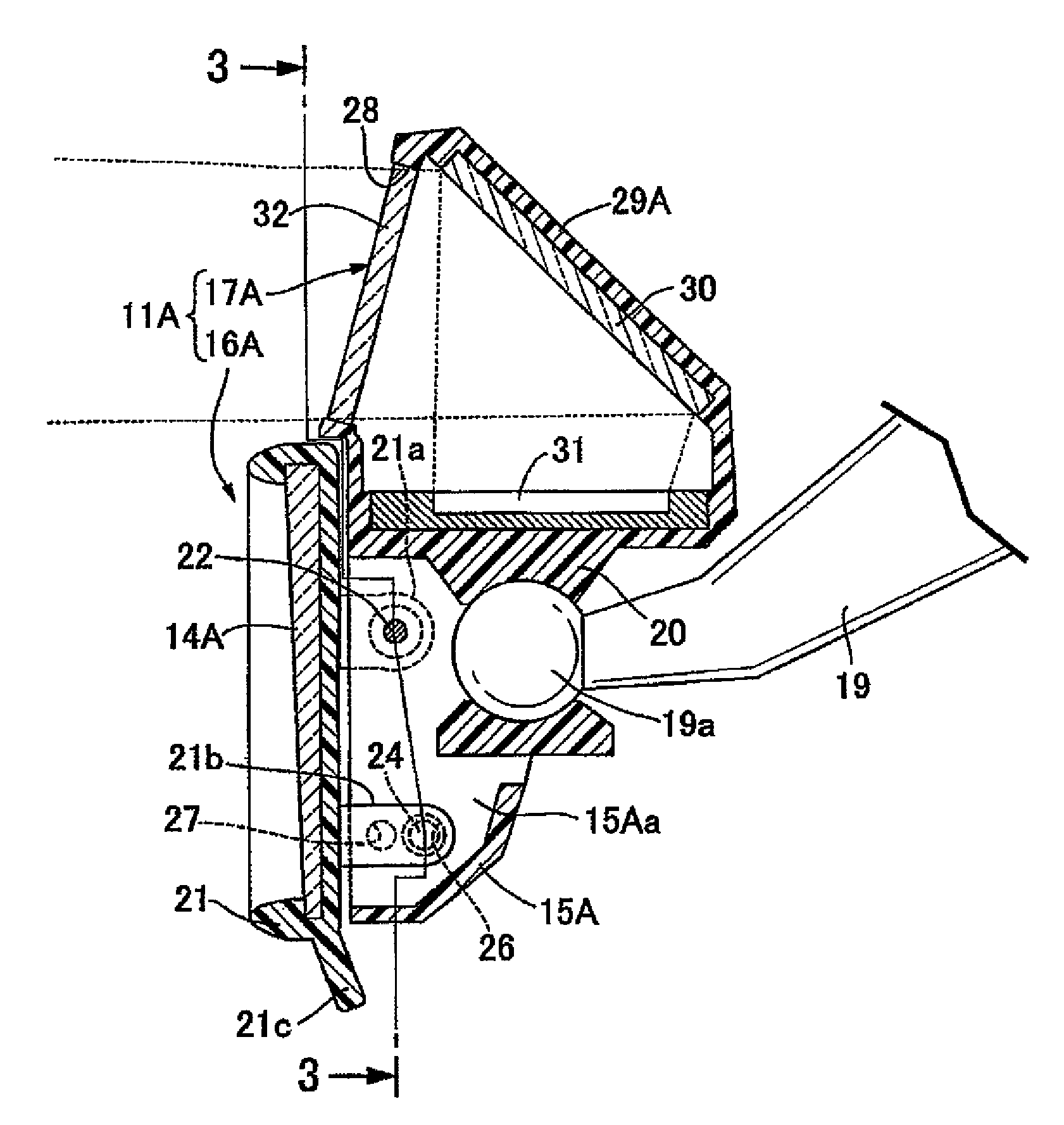
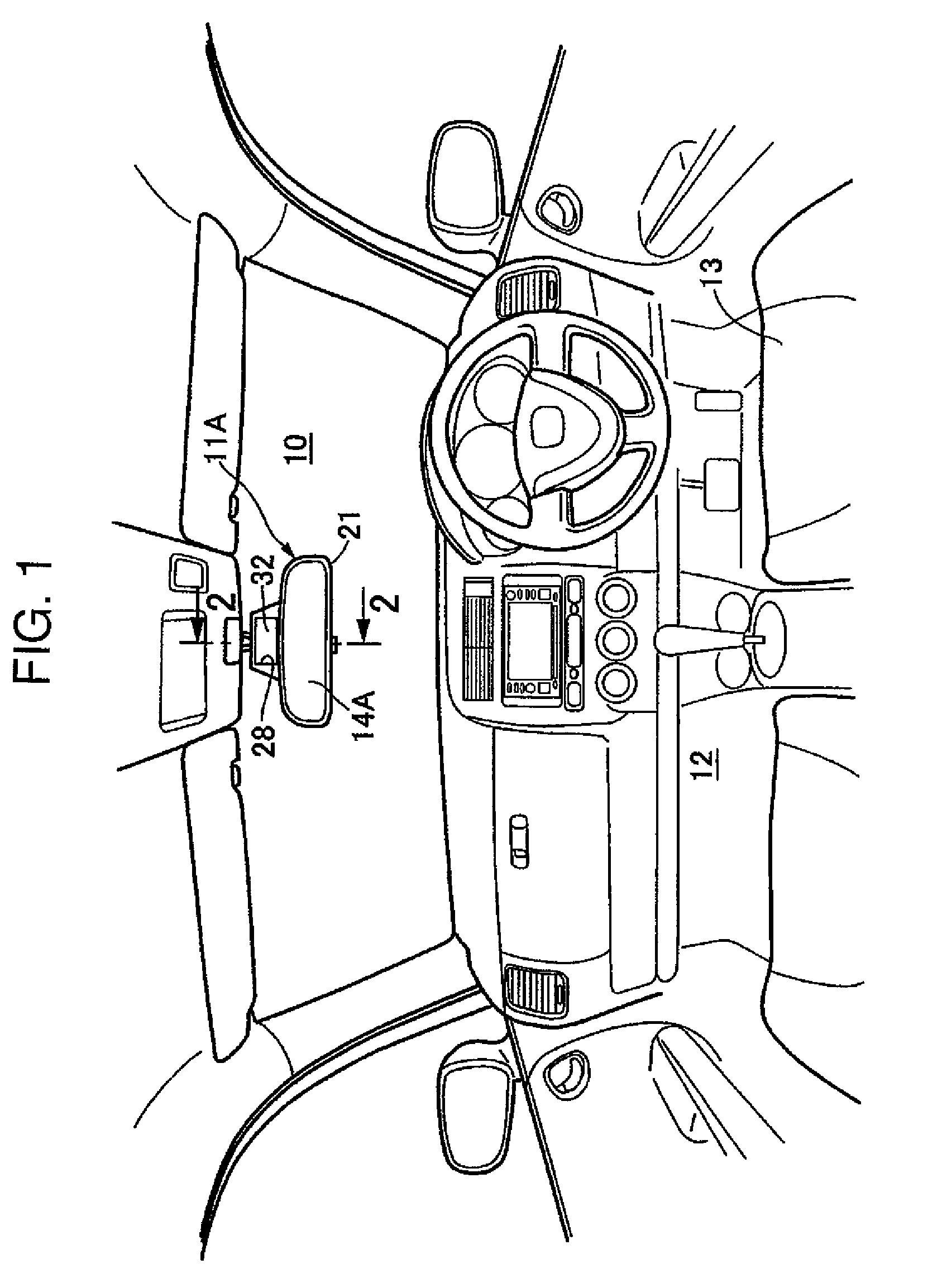
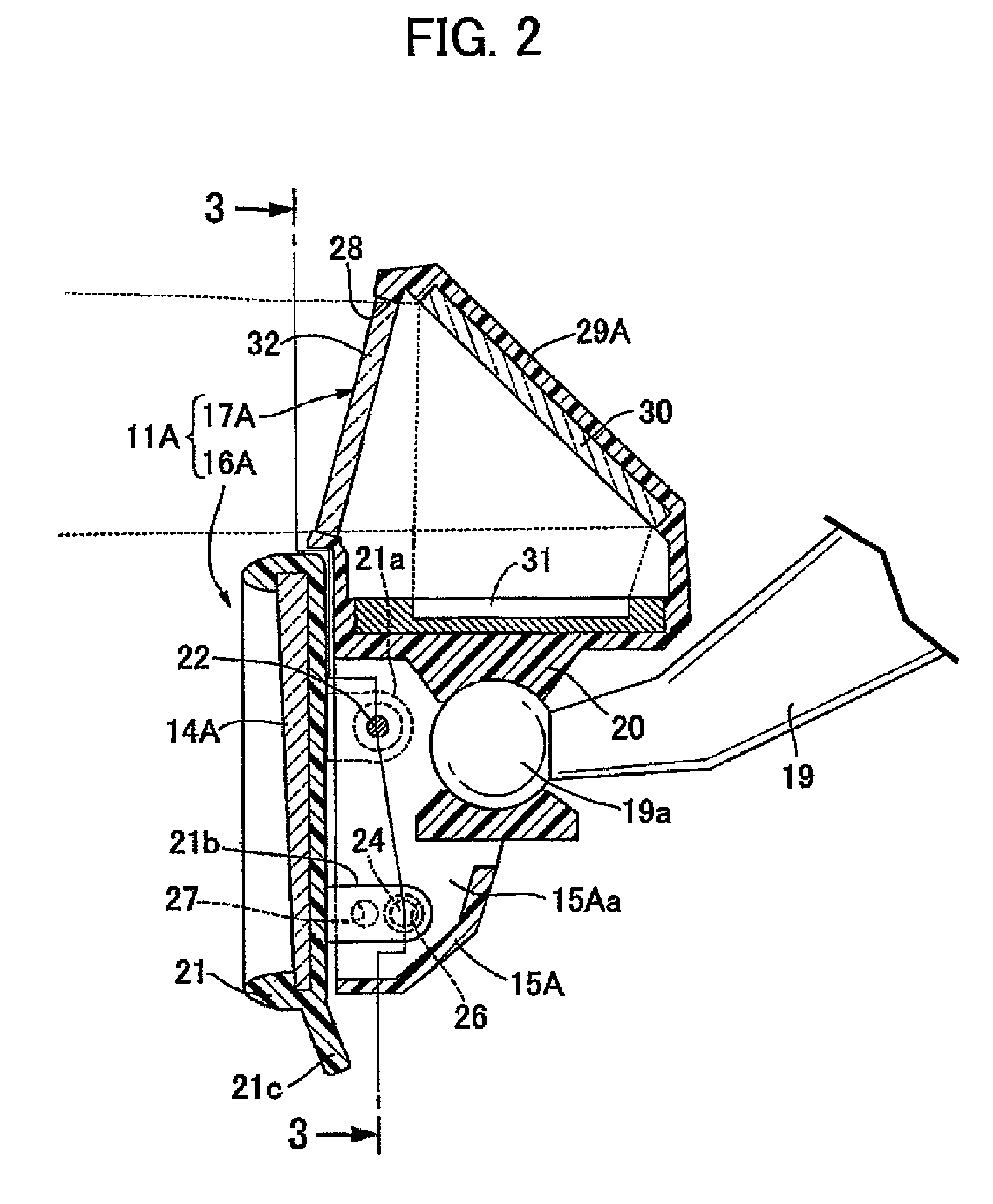
[0024]FIG. 1 to FIG. 3 show the invention in which FIG. 1 is a view showing a front portion in a car room from the rearward, FIG. 2 is a cross sectional view taken along line 2-2 in FIG. 1, and FIG. 3 is a partially cutaway cross sectional view along line 3-3 in FIG. 2.

[0025]At first in FIG. 1, a rear-view mirror system 11A with display device according to the invention is disposed rearward of a lateral central portion of a front glass 10, and a car driver who sits on a driver's seat 13 disposed, for example, on the front right side in a car room 12 can obtain a rearward view of a car by the rear-view mirror system 11A with display device and can visually recognize video images, for example, behind a rear door, for example, upon rearward movement of the car by a display window 28 equipped to the rear-view mirror system 11A with display device.

[0026]In FIG. 2 and FIG. 3, the rear-view mirror system 11A with display device includes a rear-view mirror device 16A having a rear-view mirr...

second embodiment

[0039]FIG. 4 and FIG. 5 show the invention in which FIG. 4 is a front elevational view of a rear-view mirror system with display device and FIG. 5 is a cross sectional view taken along line 5-5 in FIG. 4.

[0040]A rear-view mirror system 11B with display device includes a rear-view mirror device 16B having a rear-view mirror 14B held in a mirror housing 15B made of a synthetic resin for obtaining a rearward view of a car and a display device 17B non-movably attached to rear-view mirror device 16B for displaying information different from that of the rearward view obtained by the rear-view mirror 14B.

[0041]The mirror housing 15B is swivelably supported to a housing support portion 19 on the side of a car body. That is, an attaching portion 34 for fitting a spherical portion 19a at the top end of the housing support portion 19 is disposed to the mirror housing 15B, and the spherical portion 19a is fitted to the attaching portion 34, by which the mirror housing 15B is swivelably supporte...


PUM


Abstract

In a rear-view mirror system with display device in which a display device is attached to a rear-view mirror device disposed in a car room, a display device includes a display housing having a display window disposed at the periphery of a rear-view mirror and disposed in contiguous with a mirror housing, a light reflection device faced to the display window and disposed in the display housing, and a emission display device faced to the light reflection device and disposed in the display housing, in which a relative arrangement for the display window, the light reflection device, and the emission display device is determined such that emission display information displayed by the emission display device and reflected on the light reflection device transmits the display window, whereby the system can use an emission display device of low luminance while sufficiently ensuring the rearward view by the rear-view mirror, and can obtain emission information at the display window while decreasing the feeling of distance relative to images reflected on the rear-view mirror.

Description

BACKGROUND OF THE INVENTION[0001]1. Field of the Invention[0002]The present invention concerns a rear-view mirror system with display device in which a rear-view mirror for obtaining a rearward view of a car is held in a mirror housing, and a display device for displaying information different from that of the rearward view obtained at the rear view mirror is attached to a rear-view mirror device disposed in a car room.[0003]2. Description of the Related Art[0004]Rear-view mirror systems disposed in a car room and provided with a display device such as for televisions, clocks, images behind car upon rearward movement of the car, and navigation system have been known so far. Japanese Unexamined Utility Model Publication No. 54-33550 discloses a system in which a display device is disposed to the outer lateral side of a rear-view mirror and Japanese Unexamined Patent Publication No. 08-175263 discloses a display device including a display window disposed on a plane identical with that...

Claims


Application Information

Patent Timeline
Patent Type & Authority Patents(United States)
IPC IPC(8): G02B5/08
CPCB60R1/04B60R1/12B60R11/0235B60R2001/1215B60R2011/0033B60R2011/0064
Inventor SAKAMOTO, HIROSSHI
Owner HONDA LOCK MFG CO LTD
Why Eureka
Try Eureka