Battery with electronic compartment

a battery and electronic compartment technology, applied in the field of electronic circuitry, can solve the problems of affecting the ergonomic characteristics of the user, affecting the use of the user's comfort, and creating numerous obstacles when adding new and possibly unrelated functionality to the commonly used item

Active Publication Date: 2012-11-13
MONTEREY RES LLC
View PDF16 Cites 350 Cited by
  • Summary
  • Abstract
  • Description
  • Claims
  • Application Information

AI Technical Summary

Benefits of technology

[0010]An Electronic Containment (EC) battery includes a battery section and an electronic section that together form a standard battery form factor that allows insertion into conventional electronic devices. In one example, the electronic section can include Radio Frequency (RF) circuitry that enables electronic operations in the electronic containment battery to be communicated or controlled wirelessly. In another example, the electronic section can include wireless charging circuitry that enables the battery section to be wirelessly charged while the EC battery is inserted into the conventional electronic device. In yet another example, the electronic section can include the RF circuitry and the wireless charging circuitry.

Problems solved by technology

In many cases, this trend results in the viability of adding wireless functionality to existing products to either add features or overcome limitations of the device.
Adding new and possibly unrelated functionality to commonly used articles creates numerous obstacles.
Attaching a wireless locator device to the top or bottom of the remote control device disrupts these ergonomic characteristics, including disrupting any balancing aspects of the remote, the way the remote may rest on a coffee table or on top of a television, and the way that the remote is normally operated.
For example, it may not be possible for the operator to hold the remote and press the buttons at the same time with the same hand, since the wireless device may obstruct certain movements of the fingers on the top of a remote control key pad.
Integrating wireless functionality inside a device at the factory burdens all manufactured devices with the cost of the additional functionality, which may only be used by a fraction of the purchasers.
It is often either cumbersome or impossible to add the desired functionality to an existing device, particularly if no external data interface is provided.
Various accessories have been marketed implementing this function, but they have not been particularly successful because of the difficulty of attaching a universal external IR receiver to the multiplicity of different remote control form factors.
It is not generally possible for a user to determine battery life.
It is also not possible to turn a battery off other than by removing the battery from the device it is powering.

Method used


Image

  • Battery with electronic compartment
  • Battery with electronic compartment
  • Battery with electronic compartment

Examples


Embodiment Construction

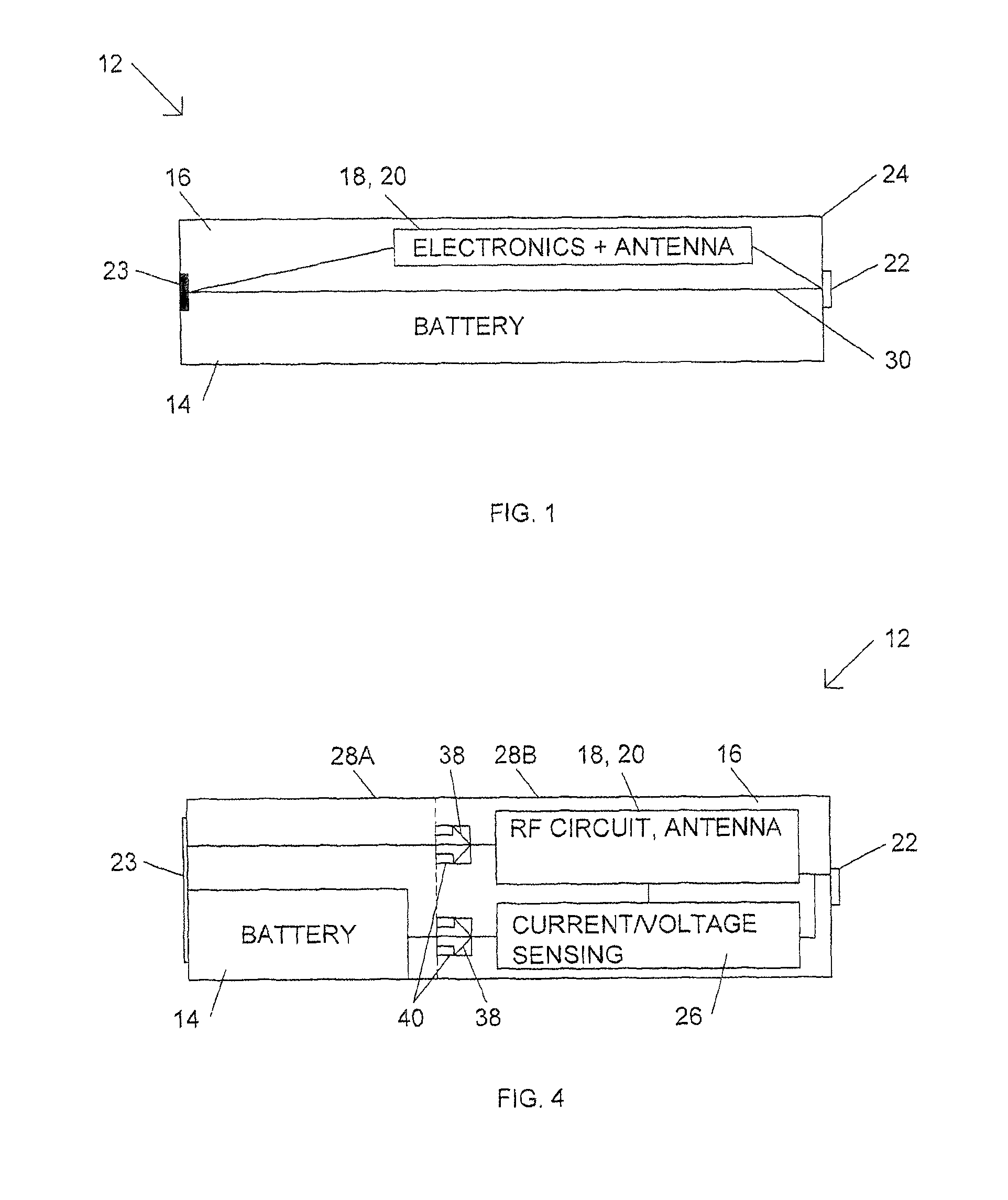
[0033]An Electronic Containment (EC) battery has a standard battery form factor and contains both a battery section holding a Direct Current (DC) battery and a separate electronic section for providing electronic functionality such as a wireless capability. The EC battery allows electronic features, such as wireless operations, to be added to existing battery operated devices without impacting the physical form factor of the device.

[0034]Batteries come in many form factors, but the majority of batteries use standard form factors, such as AAA, AA, 9V, C, D cells and watch batteries. A variety of battery technologies, including both one-time use and rechargeable, are available for each of these common battery form factors. The power density of these various battery technologies varies. It is generally possible to provide adequate power density in a smaller form factor than a particular battery-powered device needs, simply by using a marginally more expensive battery technology.

[0035]F...


PUM


Abstract

An electronic containment battery includes a battery section and an electronic section that together form a standard battery form factor that allows insertion into conventional electronic devices. In one example, the electronic section can include Radio Frequency (RF) circuitry that enables electronic operations in the electronic containment battery to be communicated or controlled wirelessly. In another example, the electronic section can include wireless charging circuitry that enables the battery section to be wirelessly charged while the EC battery is inserted into the conventional electronic device. In yet another example, the electronic section can include the RF circuitry and the wireless charging circuitry.

Description

CROSS REFERENCE TO RELATED APPLICATIONS[0001]The present application is a continuation-in-part of U.S. patent application Ser. No. 12 / 118,622, filed on May 9, 2008, which is a continuation of U.S. patent application Ser. No. 10 / 839,822, filed on May 5, 2004, which claims priority to U.S. Provisional Patent Application No. 60 / 468,541, filed on May 6, 2003, all of which are hereby incorporated by reference in their entirety.TECHNICAL FIELD[0002]The present invention relates generally to electronic circuitry and more particularly to wireless control devices powered with batteries.BACKGROUND OF THE INVENTION[0003]As the cost and physical form factor of radio-frequency (RF) components and subsystems has fallen, and integration and available bandwidth has risen, many new applications of wireless technology have become practical and / or commercially viable. In many cases, this trend results in the viability of adding wireless functionality to existing products to either add features or over...

Claims


Application Information

Patent Timeline
Patent Type & Authority Patents(United States)
IPC IPC(8): H02J7/00
CPCG08C17/02G08C23/04H02J7/025H02J17/00G08B21/0219G08B21/025H01M2/1022H01M10/482H02J50/23H02J50/30H02J50/80H02J7/00034Y02E60/10H02J7/0045H02J50/12G01R31/382H02J7/00
Inventor WRIGHT, DAVID G.
Owner MONTEREY RES LLC
Why Eureka
Try Eureka