Monitoring device for a tracking system

a tracking system and monitoring device technology, applied in the field of monitoring devices for tracking systems, can solve the problems of easy loss or theft of articles, rendering them useless

Inactive Publication Date: 2012-11-13
DEUT POST AG
View PDF10 Cites 17 Cited by
  • Summary
  • Abstract
  • Description
  • Claims
  • Application Information

AI Technical Summary

Benefits of technology

[0012]With the aid of the monitoring device for a tracking system adapted for use in at least one vehicle as well as a tracking system equipped with such a monitoring device the overall package tracking visibility and vehicle localization may be increased enormously. As an effect a dynamic and therefore optimized routing of couriers and rerouting of packages is possible.
[0015]The RFID tags may comprise passive, semi-passive, or active RFID tags that respond, when interrogated by the monitoring device, with a unique identification code. The passive RFID tags contain no power source, deriving power inductively from the RF (radio frequency) signal transmitted by the monitoring device. The range of a passive RFID tag varies from a few inches to a few meters, depending on the monitoring device power output, the sensitivity of the monitoring device's receiving antenna, the operating frequency, the antenna designs of both the monitoring device and the RFID tag, and other factors. Semi-passive RFID tags include a battery or power source to power a transmitter in response to the RF signal transmitted by the monitoring device, allowing the RFID tag to send its reply over a longer distance. Active RFID tags employ a battery or power supply that powers the RFID tag's receiver, transmitter, and other circuitry, allowing a more sensitive receiver and providing a transmitter with higher power to give the active RFID tag a maximum range. Thus, passive, semi-passive, or active RFID tags may be employed individually or in combination to provide for short, medium, or long usable range with a given monitoring device.
[0018]In an exemplary embodiment of the present invention, the monitoring device further comprises a user interface, e.g. simple web interface, for displaying messages to and receiving input from a user, the user interface being electrically connected to said control circuit. The interface may enable a user, e.g. an employee, to draw up a periodical package inventory that can be dynamically completed as the vehicle is in transit to a scheduled destination.
[0020]Information comprising the RFID tag data and the location data as well as a corresponding time stamp may be displayed to a user as real-time data or on demand as historic data. Data provided as real-time data may eventually enable intervention when an alarm activates, e.g. by a small audible siren. Data provided as historic data may enable a user to draw up reports and / or statistics.
[0021]The microprocessor may be adapted to generate a time stamp related to the RFID tag data and the location data in regular time intervals and storing the data in the memory. This feature has the effect that said articles are tracked regularly at several times besides the time of the recent handling by the staff or distribution facility.
[0042]The monitoring device may employ the microprocessor to operate a monitoring device transceiver, to manage the RFID tags, and to drive a user interface. The microprocessor allows a user to interactively add or remove the RFID tag identification codes from the monitoring device memory, and to activate and deactivate stored RFID tags.

Problems solved by technology

Such articles may be easily lost or stolen if accidentally unloaded, left behind or misplaced.
While article finder systems can be a great help in finding lost articles, the article finder systems are typically used in reaction to a loss of a single article and not in a manner to prevent the loss of a multitude of articles.
The article finder RFID tag ceases to function when its battery dies, rendering it useless.

Method used


Image

  • Monitoring device for a tracking system
  • Monitoring device for a tracking system

Examples


Embodiment Construction

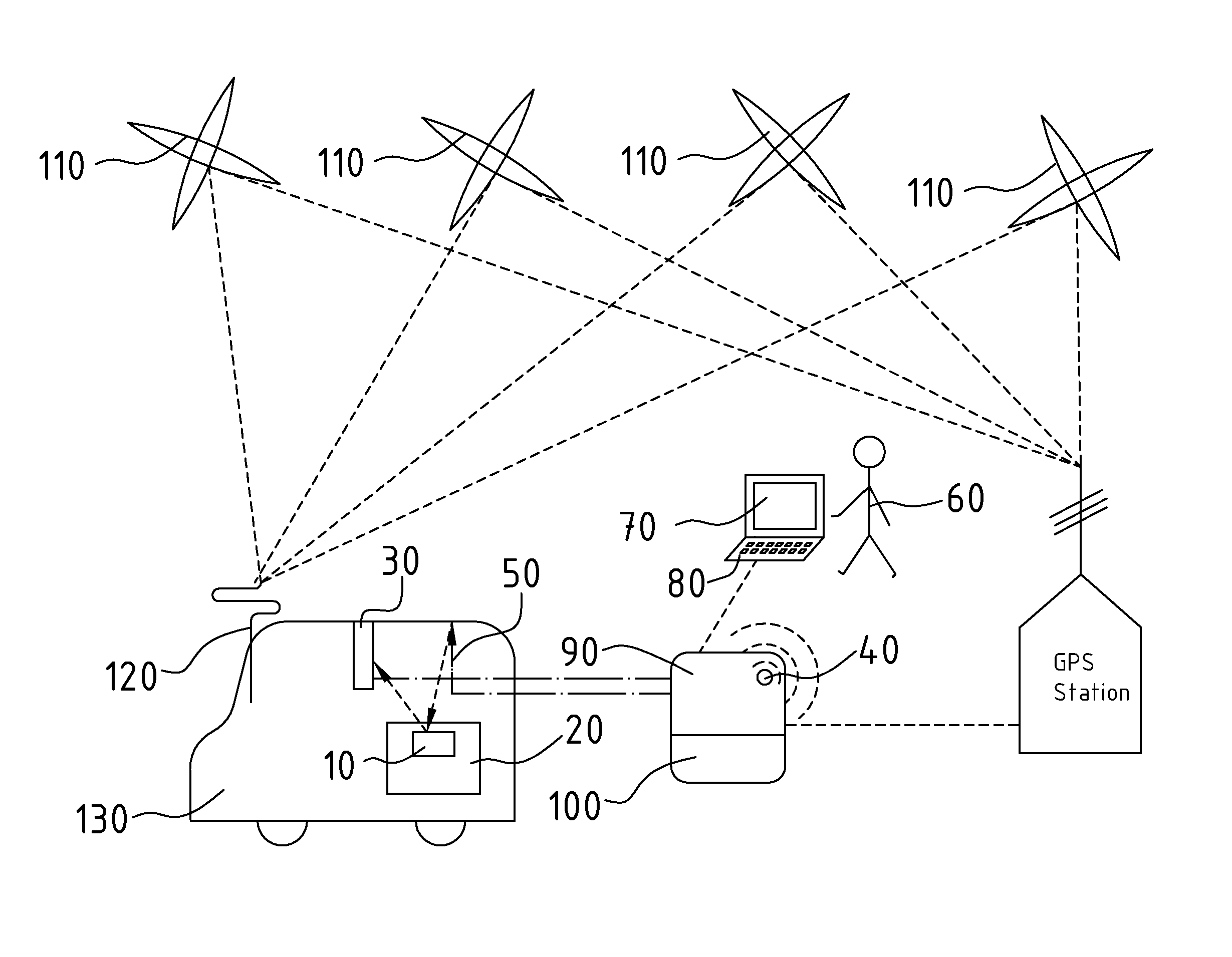
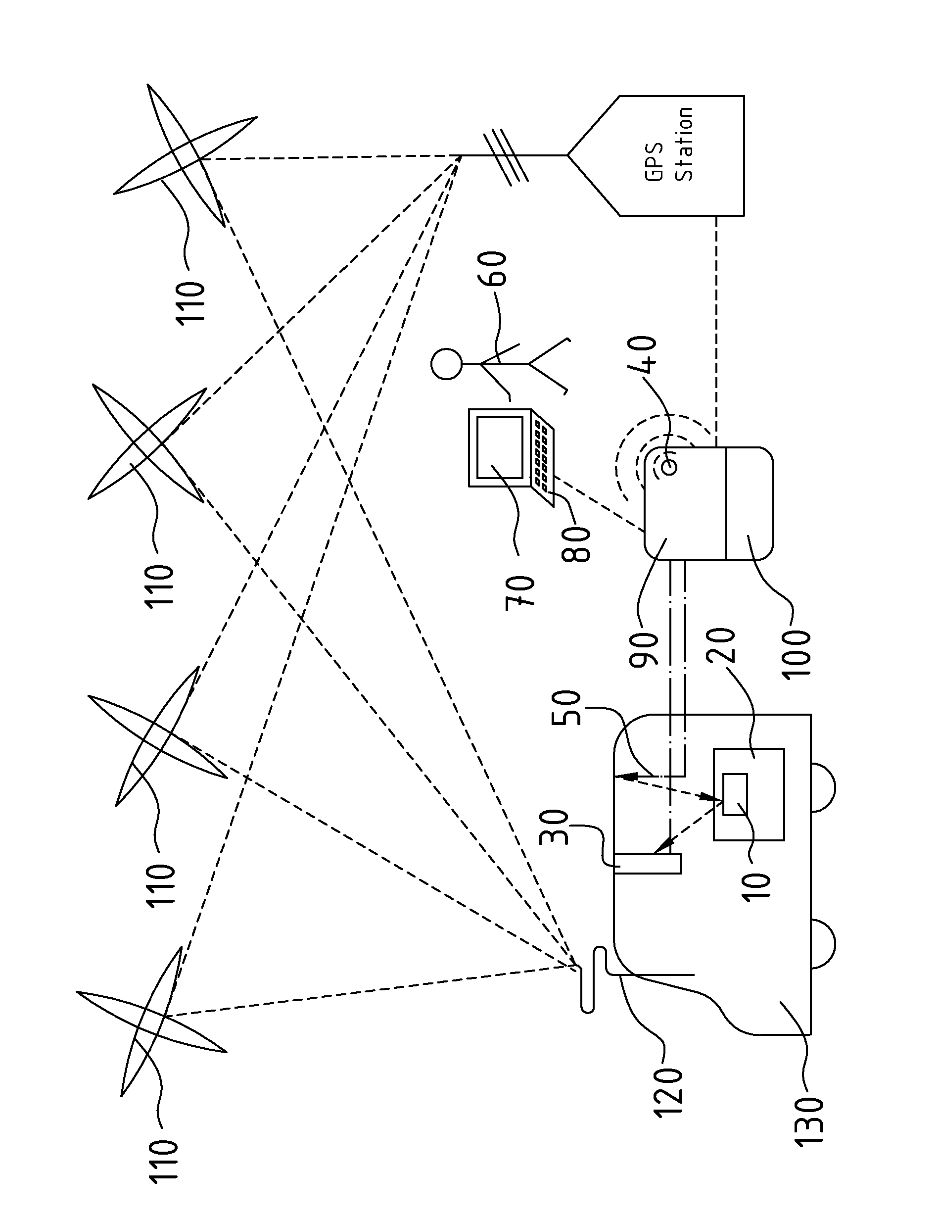
[0044]Illustrated in FIG. 1, an exemplary tracking system adapted for use in a vehicle 130 includes a monitoring device that communicates with a RFID (radio frequency identification) tag 10, which may also be referred to as transponder that may be affixed to, or contained within, an article 20 to prevent the loss of the article.

[0045]The monitoring device periodically interrogates the RFID tag 10, sending an RF signal from a RFID antenna 50 that is received by the RFID tag 10. When interrogated, the RFID tag 10 sends a response to the RFID reader 30, the response including a unique identification code. The RFID reader 30 verifies that the RFID tag 10 responds to the interrogation. If the RFID tag 10 does not respond to the interrogation, the monitoring device sounds an alarm. Thus, given a finite distance that the RFID antenna 50 of the monitoring device can transmit its interrogation signal, as well as a (typically shorter) finite range that the RFID tag 10 can transmit its respons...


PUM


Abstract

A monitoring device for a tracking system is described. The device includes a: communication circuit for communication with radio frequency identification (RFID) tag on an article to-be transported by the vehicle, and a-position system (PS) circuit for determining vehicle location. The device includes a control circuit having a microprocessor and a memory, and electrically connected to the communication and PS circuits. The microprocessor acquires tag data and location in memory, and operates the communication circuit to: interrogate tag, operate the PS circuit to determine vehicle location, and associate tag data with vehicle location The device includes an alarm electrically connected to the microprocessor. The device determines, approximates, distance from the tag to device, based on received signal strength, or time delay in receiving the tag's response, and activates the alarm if a distance threshold from tag to device is exceeded. This threshold is lower than the maximum range of the tag.

Description

CROSS REFERENCE TO RELATED APPLICATIONS[0001]Pursuant to 35 U.S.C. §371, this application is the United States National Stage Application of International Patent Application No. PCT / EP2008 / 002204, filed on Mar. 19, 2008, the contents of which are incorporated by reference as if set forth in their entirety herein, which is entitled to the benefit of U.S. Provisional Patent Application No. 60 / 919,714, filed Mar. 22, 2007, the contents of which are incorporated by reference as if set forth in their entirety herein.BACKGROUND[0002]Providing a high level of tracking visibility when articles, e.g. mailed items, packages, cargo etc., are transported by vehicles is a task which has been faced for a long time. Such articles may be easily lost or stolen if accidentally unloaded, left behind or misplaced. With a higher tracking visibility of the articles it is possible to reduce the number of lost or stolen articles.[0003]Various individual sensors for tracking an article have been on the mark...

Claims


Application Information

Patent Timeline
Patent Type & Authority Patents(United States)
IPC IPC(8): G08G1/123
CPCG06Q10/08
Inventor JOHNSON, BRIAN
Owner DEUT POST AG
Why Eureka
Try Eureka