Object detection apparatus

a technology of object detection and object, applied in the field of object detection apparatus, can solve the problems of difficult to detect the target object, difficult to acquire the correct detection, and part of the target object, and achieve the effect of reducing the mistaken detection and high object detection precision

Active Publication Date: 2012-11-13
NEC CORP
View PDF25 Cites 4 Cited by
  • Summary
  • Abstract
  • Description
  • Claims
  • Application Information

AI Technical Summary

Benefits of technology

[0020]By virtue of the configurations as described hereinabove, the present invention is able to restrain the mistaken detection in detecting the object from inside an image and, at the same time, mend the undetectable problem, thereby facilitating a high precision of object detection.

Problems solved by technology

Further, a problem occurs that it is difficult to acquire a correct detection result when the background changes due to illuminative variation and the like.
However, with the interframe difference method, a problem occurs that only part of a target object (an outline and the like) can be detected with some image pattern of the target object.
Further, with a motionless target object, another problem occurs that because the interframe image almost does not change, it is difficult to detect the target object.
However, with the method disclosed in the Patent Document 1 described hereinabove, a problem occurs that when the target object moves slowly at times and stops at other times, the target object will be updated by the background image, thereby making it difficult to detect the target object.
Further, the background update cannot catch up with a background which changes continuously such as with a wobbling tree, a fluctuant water surface, and the like (environmental changing).
Thereby, it is difficult to appropriately detect the target object.
However, with the technologies disclosed in the patent documents and nonpatent document described hereinabove, there are problems as described hereinbelow.
The first problem is that there is a case that a part of the target object includes a pixel value similar to the background, thereby lowering the detection performance.
The reason is that especially with the technology disclosed in the Nonpatent Document 1, even viewing from the background expressed by a mixture distribution model, it is still impossible to distinguish the portion of the object with a pixel value similar to the background from the ordinary background.
Further, because of this, the pixel value of the target object mistakenly recognized as the background will be updated as the background, thereby lowering the estimation precision of the mixture distribution model for the background, and thereby affecting the object detection.
The second problem is that when the trend of the background changes in part for an instant (for example, when the wind changes in intensity instantaneously so that part of the tree changes in the manner of wobbling for an instant), during that instant, a small area of the background may be mistakenly detected as the object.
The reason is that especially with the technology disclosed in the Nonpatent Document 1, even viewing from the background expressed by a mixture distribution model, it is still impossible to distinguish the small area of the background mistakenly detected from the ordinary foreground (target object).
Further, utilizing the technologies of the Patent Documents 2 and 3 described hereinbefore cannot solve those two problems either.

Method used


Image

  • Object detection apparatus
  • Object detection apparatus
  • Object detection apparatus

Examples


first exemplary embodiment

[0029]Detailed explanations will be made in reference to FIGS. 1 to 5 with respect to an object detection apparatus, an object detection method, and a computer program in accordance with a first exemplary embodiment of the present invention.

[0030][Configurations]

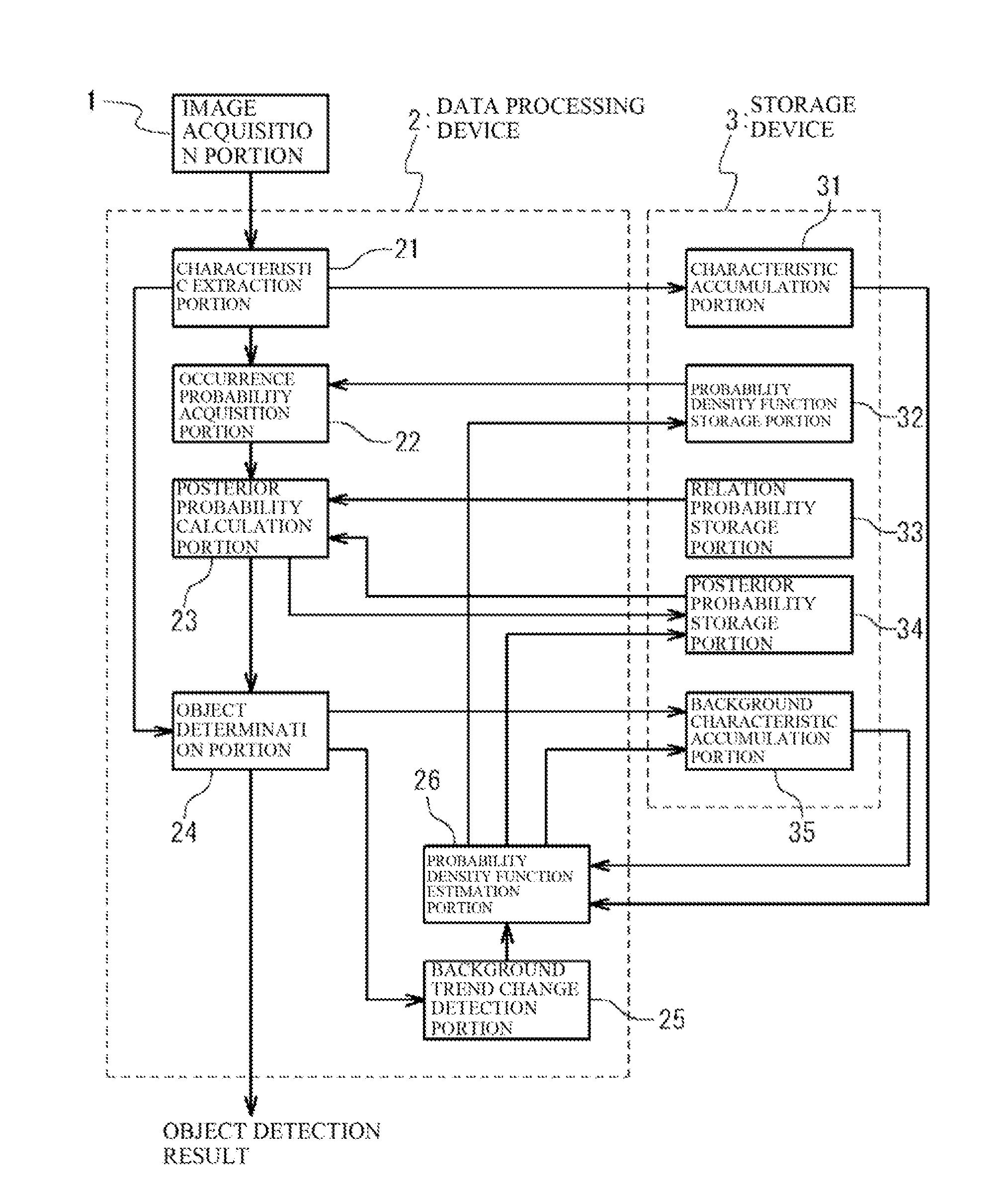
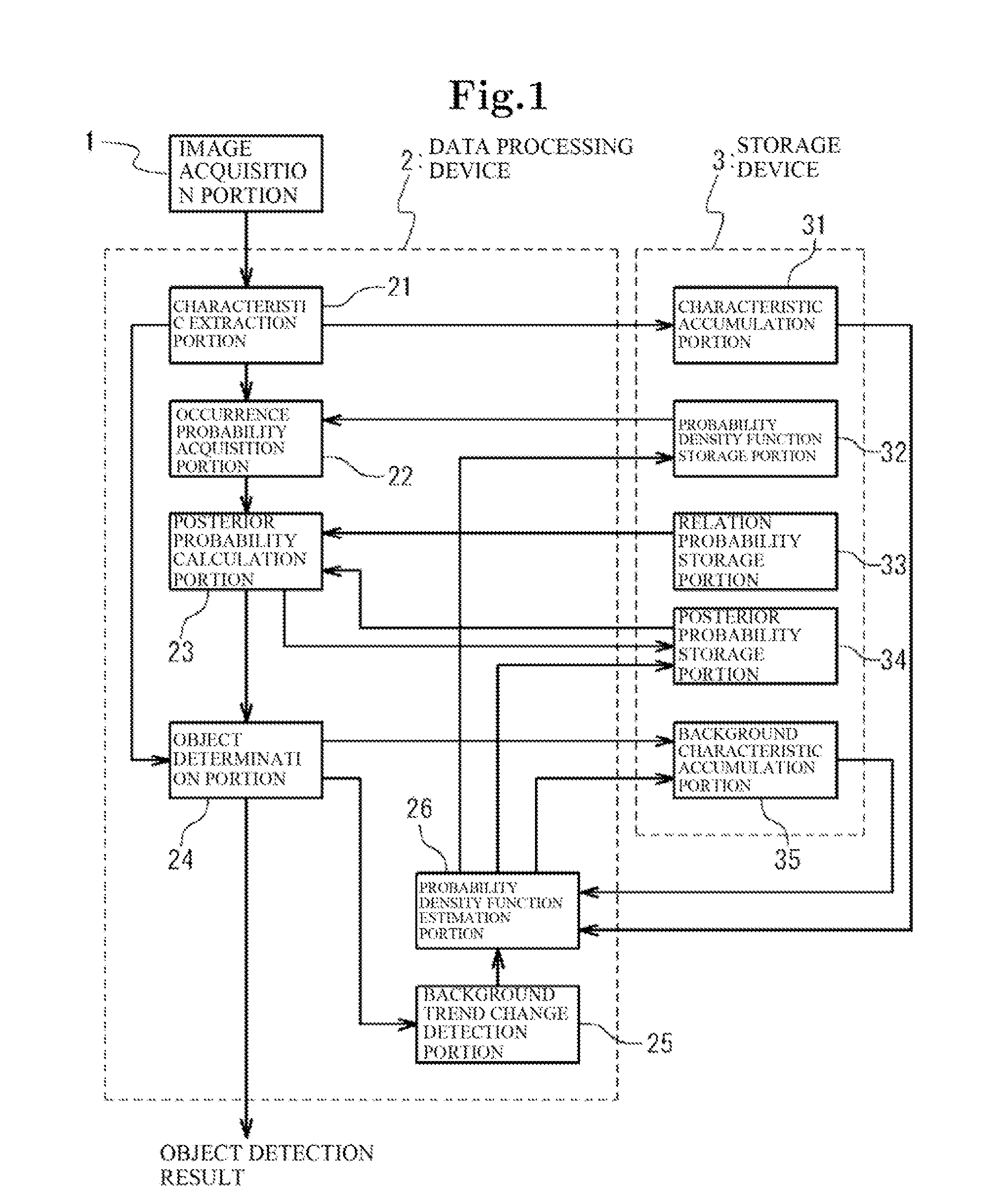
[0031]In reference to FIG. 1, an object detection apparatus in accordance with the first exemplary embodiment of the present invention includes an image acquisition portion 1 for acquiring an image from a moving image of a camera, video, and the like, a data processing device 2 operative under computer control, and a storage device 3 for storing information.

[0032]Then, the storage device 3 includes a characteristic accumulation portion 31, a probability density function storage portion 32, a relation probability storage portion 33, a posterior probability storage portion 34, and a background characteristic accumulation portion 35. Hereinbelow, each configuration will be further described in detail.

[0033]The characteristic ac...

second exemplary embodiment

A Second Exemplary Embodiment

[0067]Next, a detailed explanation will be made with respect to an object detection apparatus in accordance with a second exemplary embodiment of the present invention in reference to FIG. 6.

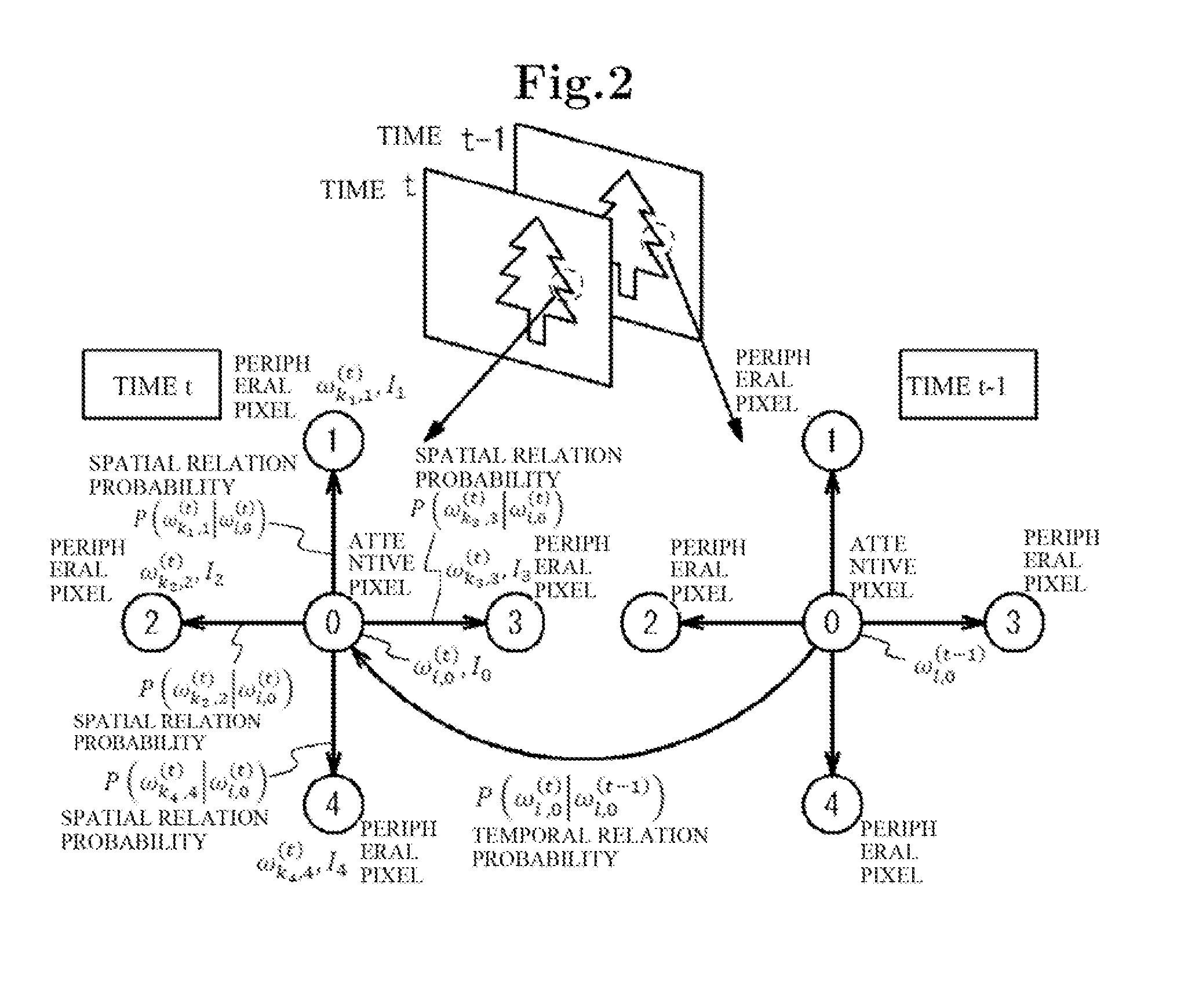
[0068]In reference to FIG. 6, the object detection apparatus in accordance with the second exemplary embodiment of the present invention includes a data processing device 200 which adds a relation probability calculation portion 27 to the data processing device 2 in the first exemplary embodiment shown in FIG. 1, and a storage device 300 which removes the relation probability storage portion 33 from the storage device 3 in the first exemplary embodiment shown in FIG. 1. That is, in the first exemplary embodiment described hereinbefore, the spatial relation probability and the temporal relation probability were configured in a fixed manner. However, as will be explained hereinbelow, it is possible to utilize the relation probability calculation portion 27 to configure...

third exemplary embodiment

A Third Exemplary Embodiment

[0073]Next, a detailed explanation will be made with respect to an object detection apparatus in accordance with a third exemplary embodiment of the present invention in reference to FIG. 7.

[0074]In reference to FIG. 7, in the object detection apparatus in accordance with the third exemplary embodiment of the present invention, the image acquisition portion 1, and the storage device 3 having the characteristic accumulation portion 31, the probability density function storage portion 32, the relation probability storage portion 33, the posterior probability storage portion 34, and the background characteristic accumulation portion 35, which are the same as those in the first exemplary embodiment, are connected with a computer 100. Further, a computer-readable storage medium 102 for storing an object detection program 101 is connected with the computer 100.

[0075]The computer-readable storage medium 102 is configured by a magnetic disk, a semiconductor memor...


PUM


Abstract

In order to improve object detection precision, an object detection apparatus includes a posterior probability calculation portion utilizing an occurrence probability of a background and a foreground acquired by utilizing a characteristic quantity extracted from each pixel of an input image and a probability density function, a posterior probability of the previous background and foreground, and a conditional probability indicating a relation of an event (background or foreground) to the vicinity of an attentive pixel in a spatial direction and a relation of an event to the vicinity of the attentive pixel in a temporal direction so as to calculate a posterior probability of the background and the foreground from a probability model utilizing a tendency that the same event appears together in the vicinity of the attentive pixel in the spatial and temporal directions; and an object determination portion for determining an object from comparison between the posterior probabilities of the background and the foreground.

Description

TECHNICAL FIELD[0001]The present invention relates generally to object detection apparatuses and, in particular, to an object detection apparatus for detecting an object from inside an image.BACKGROUND ART[0002]There are object detection methods utilized for detecting a target object from inside an image. As technologies related to the object detection methods, there are a background difference method and an interframe difference method.[0003]The background difference method detects a target object by taking out the difference of an input image from its background image (an image which does not include the target object). According to the background difference method, it is possible to successfully detect a target object which moves at times and stops at other times. On the other hand, for the background difference method, it is necessary to prepare a background image which does not include the target object in advance. Further, a problem occurs that it is difficult to acquire a cor...

Claims


Application Information

Patent Timeline
Patent Type & Authority Patents(United States)
IPC IPC(8): G06K9/00G06V10/28
CPCG06K9/3241G06K9/38G06T7/0081G06T7/0087G06T7/11G06T7/143G06V10/255G06V10/28
Inventor IKEDA, HIROO
Owner NEC CORP
Why Eureka
Try Eureka