Microwave susceptor system

a technology of susceptors and microwaves, applied in the field of microwave platforms, can solve the problems of grease or juices from food items dripping off the susceptor tray onto the microwave floor, affecting the performance of the susceptor tray, and leaking points for melting ingredients, etc., to achieve the effect of efficient cooking food in the microwav

Active Publication Date: 2012-11-20
WATKINS JEFFREY T
View PDF3 Cites 5 Cited by
  • Summary
  • Abstract
  • Description
  • Claims
  • Application Information

AI Technical Summary

Benefits of technology

[0010]A system for efficiently cooking food in a microwave. The invention generally relates to a microwave platform which includes an outer panel having a first susceptor layer and a first support layer attached to the first susceptor layer and an inner panel foldably connected to the outer panel for lining an interior surface of the outer panel, wherein the inner panel includes a second susceptor layer and a second support layer attached to the second susceptor layer. The outer panel has a raised platform and a plurality of legs foldably connected to the platform. The outer panel also includes a plurality of retainer flaps vertically extending upward from a perimeter of the platform for retaining a food item thereon. The inner panel seals a plurality of openings extending through the platform which are exposed by the flaps pivoting to a vertical position.

Problems solved by technology

Not elevating the tray and food item can decrease the performance of the susceptor tray by not allowing the tray to gather a maximum amount of heat to be transferred to the food item.
It is commonly used practice to invert the single layer susceptor tray to provide an elevated cooking surface; however this can result in an uneven platform in which to position the food item upon which can further result in grease or juices from the food item dripping off the susceptor tray onto the microwave floor.
This type of mechanism allows the food item and susceptor tray to be elevated but creates holes within the susceptor tray bottom thus creating leaking points for the melting ingredients.

Method used


Image

  • Microwave susceptor system
  • Microwave susceptor system
  • Microwave susceptor system

Examples


Embodiment Construction

A. Overview

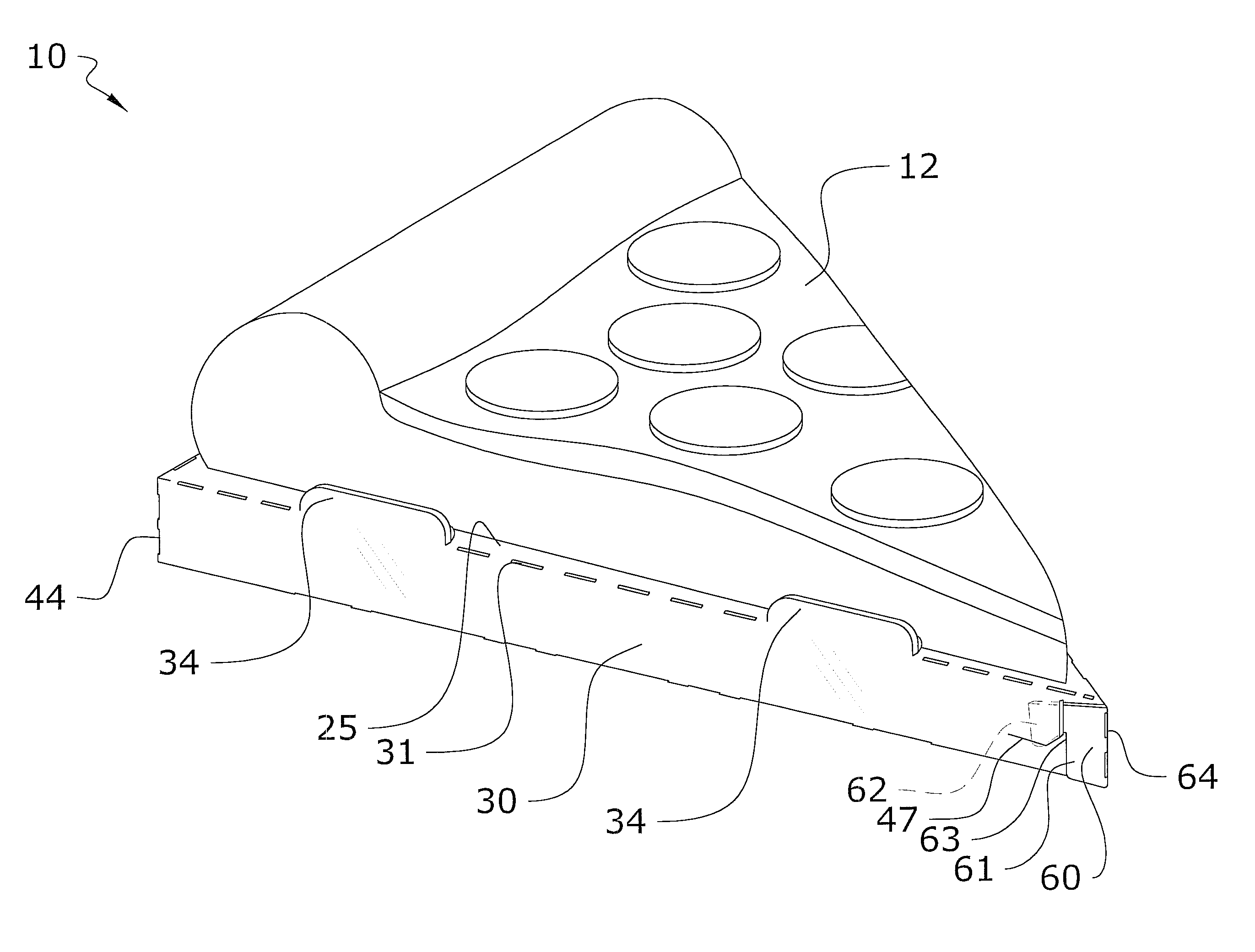
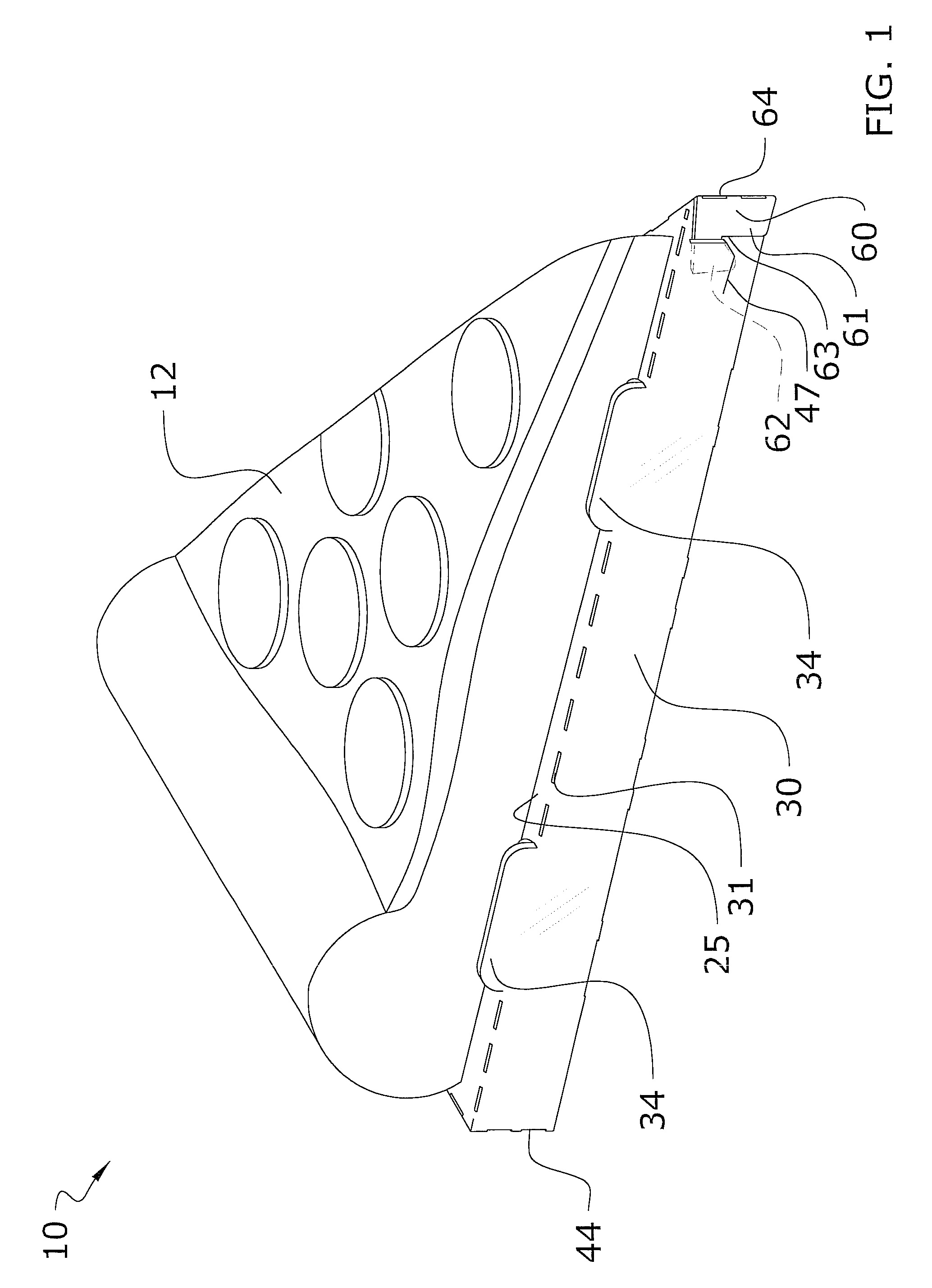
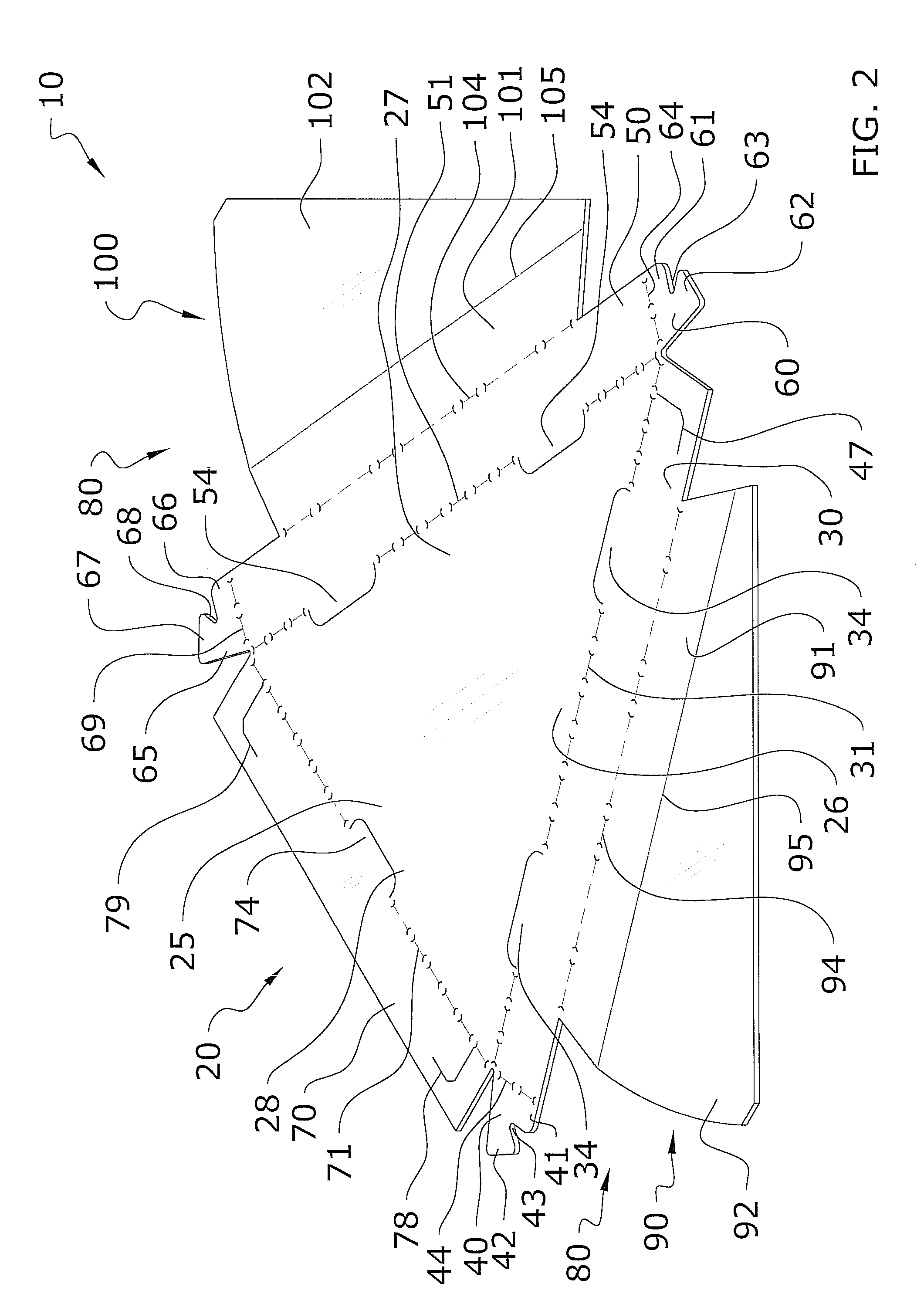
[0020]Turning now descriptively to the drawings, in which similar reference characters denote similar elements throughout the several views, FIGS. 1 through 7 illustrate a microwave susceptor system 10, which comprises an outer panel 20 having a first susceptor layer 21 and a first support layer 22 attached to the first susceptor layer 21 and an inner panel 80 foldably connected to the outer panel 20 for lining an interior surface of the outer panel 20, wherein the inner panel 80 includes a second susceptor layer 81 and a second support layer 82 attached to the second susceptor layer 81. The outer panel 20 has a raised platform 25 and a plurality of legs 30, 40, 50 foldably connected to the platform 25. The outer panel 20 also includes a plurality of retainer flaps 34, 54, 74 vertically extending upward from a perimeter of the platform 25 for retaining a food item 12 thereon. The inner panel 80 seals a plurality of openings 36, 56, 76 extending through the platform 25 whi...


PUM


Abstract

A constructable microwave susceptor sheet for holding and cooking a food item in a microwave. The constructable microwave susceptor sheet generally includes an outer panel having a first susceptor layer and a first support layer attached to the first susceptor layer and an inner panel foldably connected to the outer panel for lining an interior surface of the outer panel, wherein the inner panel includes a second susceptor layer and a second support layer attached to the second susceptor layer. The outer panel has a raised platform and a plurality of legs foldably connected to the platform. The outer panel also includes a plurality of retainer flaps vertically extending upward from a perimeter of the platform for retaining a food item thereon. The inner panel seals a plurality of openings extending through the platform which are exposed by the flaps pivoting to a vertical position.

Description

CROSS REFERENCE TO RELATED APPLICATIONS[0001]Not applicable to this application.STATEMENT REGARDING FEDERALLY SPONSORED RESEARCH OR DEVELOPMENT[0002]Not applicable to this application.BACKGROUND OF THE INVENTION[0003]1. Field of the Invention[0004]The present invention relates generally to a microwave platform and more specifically it relates to a microwave susceptor system for efficiently cooking food in a microwave.[0005]2. Description of the Related Art[0006]Any discussion of the related art throughout the specification should in no way be considered as an admission that such related art is widely known or forms part of common general knowledge in the field.[0007]Microwave platforms have been in use for years. Typically, microwaveable platforms are utilized by positioning a desired food item (i.e. sandwich, pizza, etc.) on top of the microwaveable platform and then cooking the food item in the microwave. The microwaveable platforms generally have a metallic or other heating mater...

Claims


Application Information

Patent Timeline
Patent Type & Authority Patents(United States)
IPC IPC(8): H05B6/80
CPCH05B6/6408H05B6/6494B65D81/3453B65D5/52B65D2581/3406B65D2581/3498
Inventor WATKINS, JEFFREY T.
Owner WATKINS JEFFREY T
Why Eureka
Try Eureka