
Storage system and method implementing online volume and snapshot with performance/failure independence and high capacity efficiency

a storage system and snapshot technology, applied in the field of data backup methods for storage systems, can solve the problems of reducing capacity efficiency, affecting the access capability of the latest master storage, and data in the master storage before update cannot be restored, so as to achieve high capacity efficiency

Inactive Publication Date: 2012-11-20
HITACHI LTD
View PDF15 Cites 8 Cited by
  • Summary
  • Abstract
  • Description
  • Claims
  • Application Information

AI Technical Summary

Benefits of technology

This approach enables high capacity efficiency in data backup while ensuring the latest and previous data versions remain accessible without affecting performance or failure resilience.

Problems solved by technology

The problem with the technology of Patent Document 1 is that, however, the snapshot logical disk storing the copy of the entire master logical disk means using a large amount of storage capacity of the storage system.
Especially if with a larger number of backup generations for storage, a considerable amount of storage capacity is used, thereby problematically reducing the capacity efficiency.
The problem with the technology of Patent Document 2 is that, however, for restoring the data in the master storage before update, there always needs to combine the data in the latest master storage with the data in the pile storage.
This means that the process of restoring the data in the master storage before update affects the access capabilities to the latest master storage.
What is more, when the master storage suffers from failure, the data in the master storage before update cannot be restored.

Method used


Image

  • Storage system and method implementing online volume and snapshot with performance/failure independence and high capacity efficiency
  • Storage system and method implementing online volume and snapshot with performance/failure independence and high capacity efficiency
  • Storage system and method implementing online volume and snapshot with performance/failure independence and high capacity efficiency

Examples


Embodiment Construction

[0039]An embodiment of the invention is described first in detail by referring to the accompanying drawings.

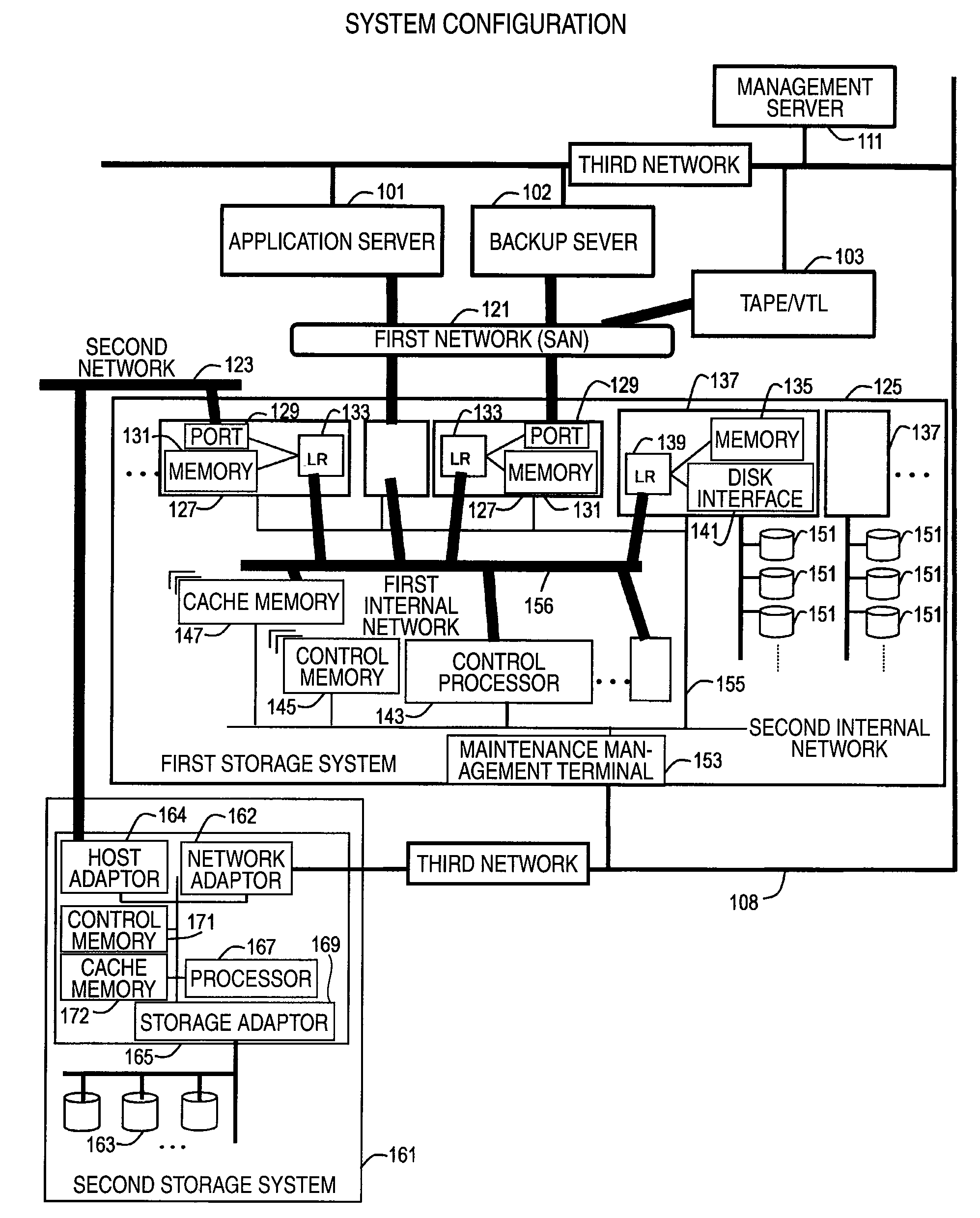
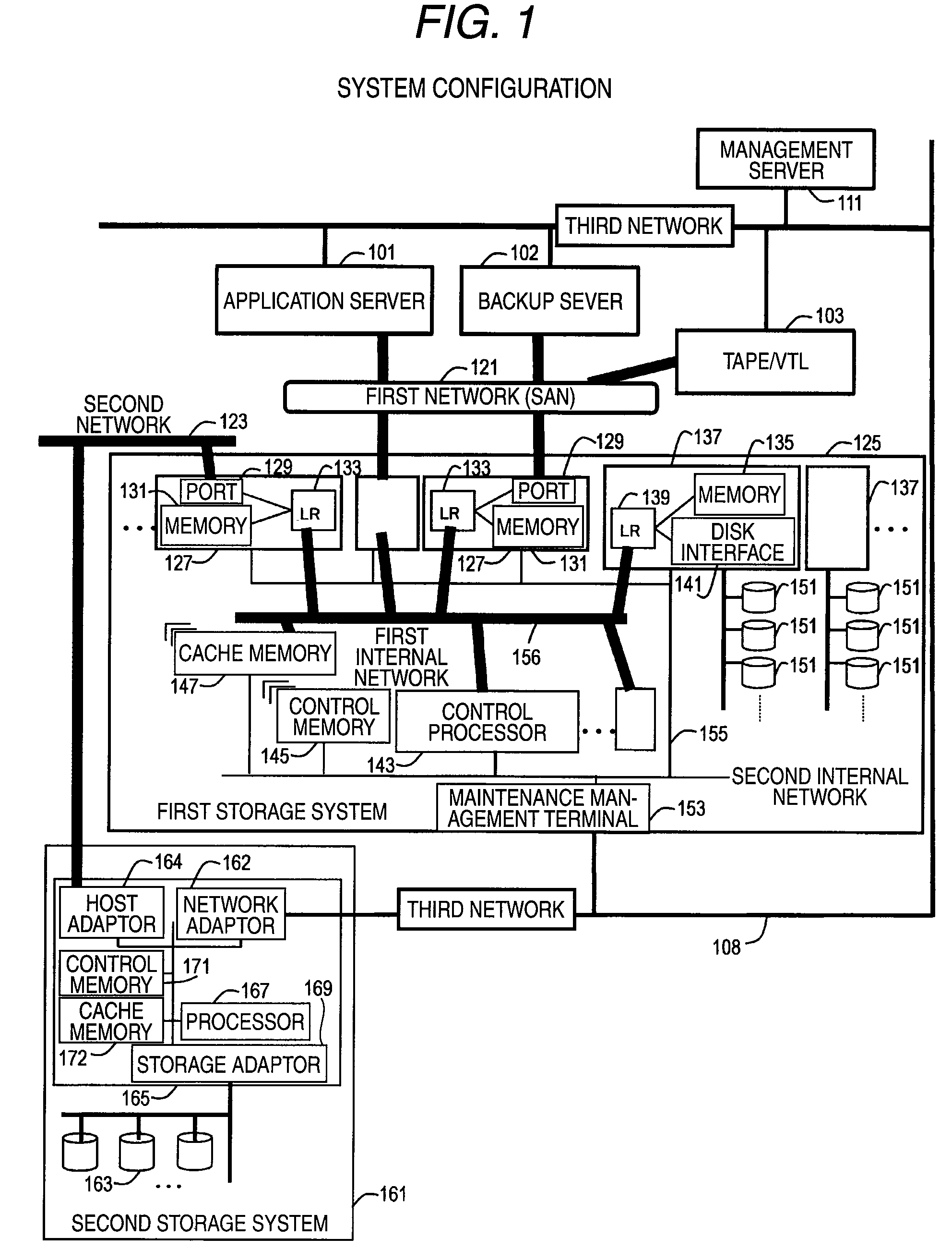
[0040]FIG. 1 is a block diagram showing the configuration of a computer system in the embodiment of the invention.

[0041]The computer system of the embodiment is configured to include an application server 101, a backup server 102, a tape device 103, a management server 111, a first storage system 125, and a second storage system 161. The first storage system 125 is coupled to the other components, i.e., the application server 101, the backup server 102, and the tape device 103, over a first network 121. The second storage system 161 is coupled to such a first storage system 125 over a second network 123. The components, i.e., the application server 101, the backup server 102, the tape device 103, the management server 111, and the first and second storage systems 125 and 161, are coupled together over a third network 108.

[0042]The first to third networks 121, 123, and 108 are ...


PUM


Abstract

A storage system for storage of data written from a computer, and when a write request of data to a first logical volume is received, the data on request is stored into the first logical volume. When a first-generation snapshot creation request is received, the data stored in the first logical volume at the time of receiving the first-generation snapshot creation request is written into a pool region as data corresponding to a first-generation snapshot, and when a second-generation snapshot creation request is received, any portion of the data updated after the first-generation snapshot creation request is received but before the second-generation snapshot creation request is issued is read from the first logical volume for writing into the pool region. Such a storage system favorably implements snapshot backup with no dependency with a positive volume in terms of performance and failure, and with high capacity efficiency.

Description

CROSS REFERENCES TO RELATED APPLICATIONS[0001]This application relates to and claims priority from Japanese Patent Application No. 2008-298423, filed on Nov. 21, 2008, the entire disclosure of which is incorporated herein by reference.BACKGROUND OF THE INVENTION[0002]1. Field of the Invention[0003]The present invention relates to a data backup method for a storage system and, more specifically, to a data backup method with application of a so-called differential snapshot technology.[0004]2. Description of the Related Art[0005]For protection of data in a storage system, various types of technologies are known for continuously backing up the data.[0006]As an example, Patent Document 1 (JP-A-2002-373093) describes the technology of copying a memory area (logical volume) in its entirety at the time of designation, and keeping the resulting copy as backup data. With such a technology, two logical volumes (logical disks in Patent Document 1) configure a mirror. Out of the two logical disk...

Claims


Application Information

Patent Timeline
Patent Type & Authority Patents(United States)
IPC IPC(8): G06F12/00
CPCG06F11/1466G06F11/1451
Inventor EGUCHI, YOSHIAKIKAWAMURA, SHUNJI
Owner HITACHI LTD
Learn More