Eureka AIR delivers breakthrough ideas for toughest innovation challenges, trusted by R&D personnel around the world.

Auxiliary drive system for a high-rail vehicle

a technology of auxiliary drive system and high-rail vehicle, which is applied in the direction of transportation and packaging, locomotives, and retractable wheels, etc., can solve the problems of reducing efficiency, requiring multiple workers to operate, and components to be replaced

Active Publication Date: 2012-11-27
B&B METALS
View PDF52 Cites 12 Cited by
  • Summary
  • Abstract
  • Description
  • Claims
  • Application Information

AI Technical Summary

Benefits of technology

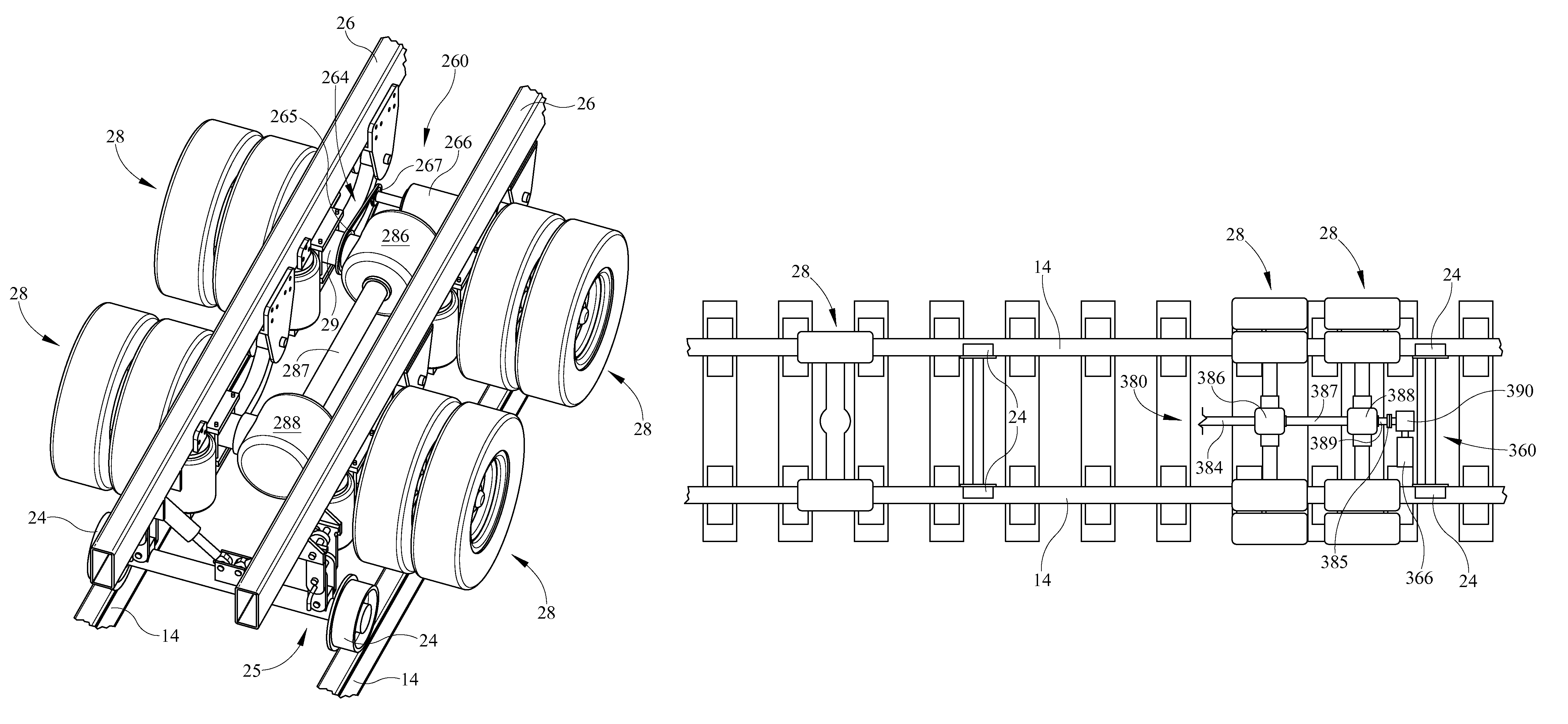
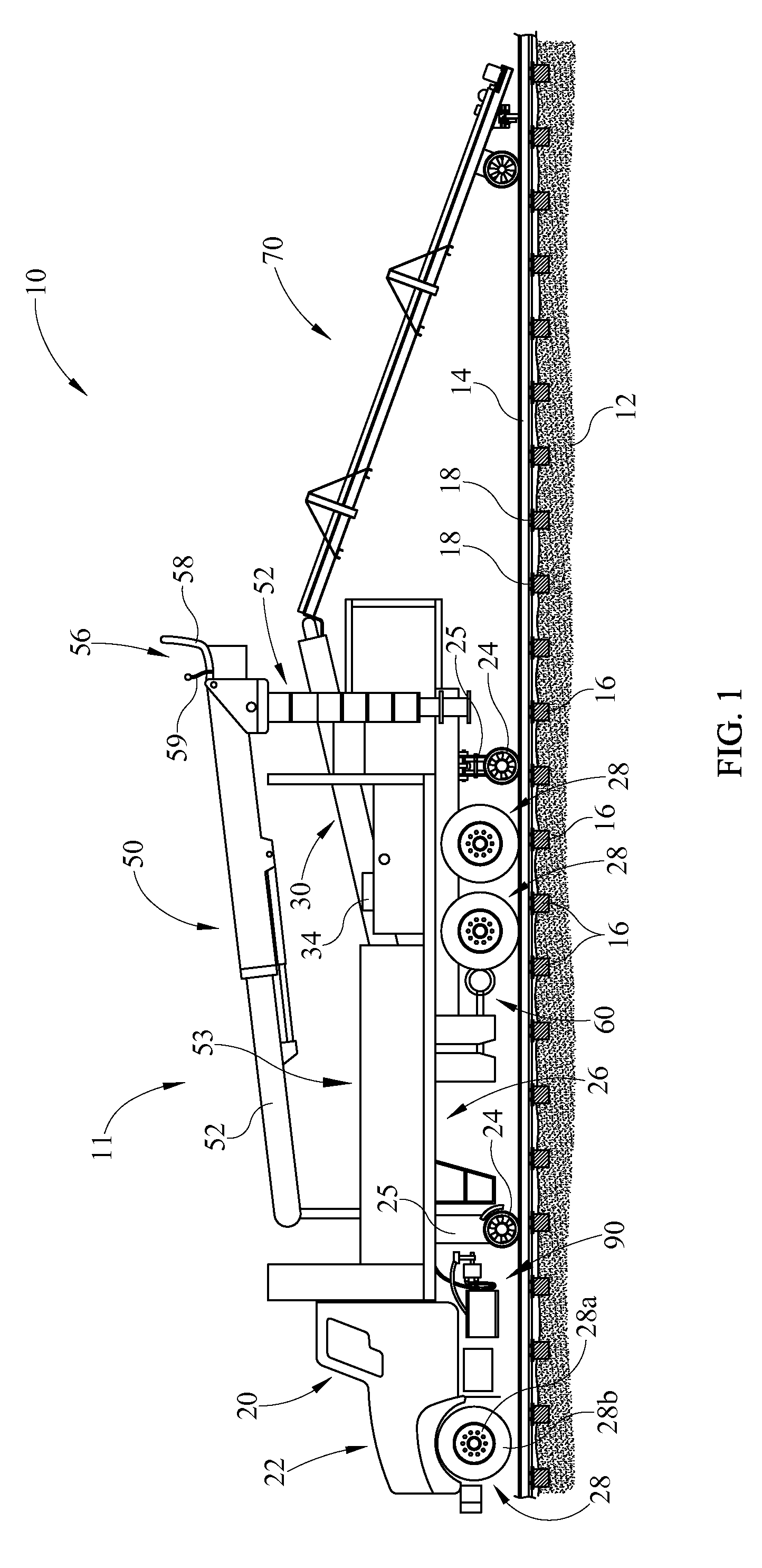
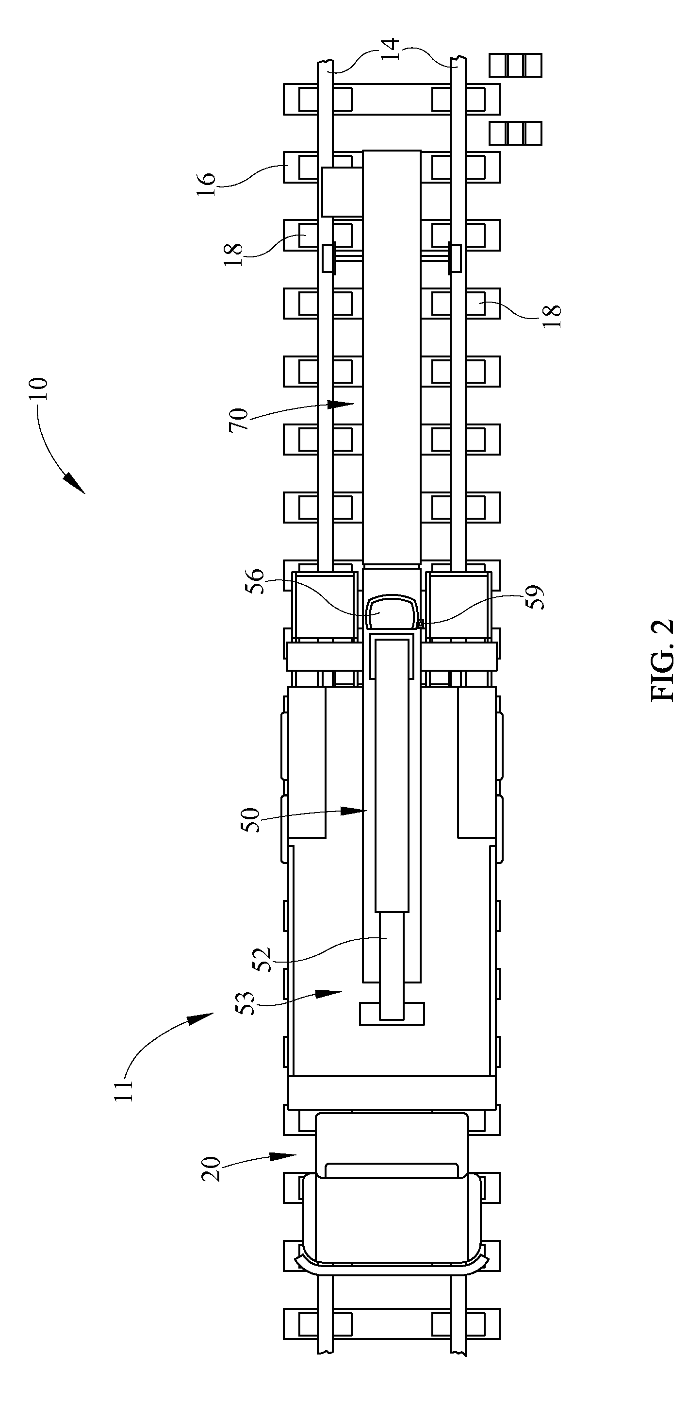
[0015]An auxiliary drive system for a high-rail vehicle comprises a high-rail vehicle having a first prime mover, a disengaged transmission, a chassis, a first set of on-road wheel assemblies and a second set of rail wheels, a cab for controlling the high-rail vehicle on road, a remote cab spaced from the primary cab, the remote cab allowing for control of the high-rail vehicle on railroad tracks, a secondary drive assembly comprising one of a hydraulic motor or an electric motor, a friction roller engaging one of the first set of on road wheel assemblies, the friction roller drivably engaging at least one of the first set of on road wheel assemblies and, the secondary drive assembly operable from the remote cab to move the friction roller and move the high-rail vehicle along the railroad tracks. The auxiliary drive system further comprising a generator when the secondary drive assembly comprises an electric motor. The auxiliary drive system further comprising a friction roller slidably engageable with one of the first on-road wheel assemblies. The auxiliary drive system wherein the one of the hydraulic or electric motor directly engages the friction roller. The auxiliary drive system wherein the secondary drive assembly further comprises a transmission. The auxiliary drive system wherein the transmission is operably connecting the friction roller and the one of a hydraulic or an electric motor. The auxiliary drive system wherein the transmission is a chain drive. The auxiliary drive system wherein the transmission is a gear drive. The auxiliary drive system wherein the transmission is a belt drive.
[0016]An auxiliary drive system comprises a high-rail vehicle having a cab, a chassis, a plurality of wheels disposed on the chassis, a transmission and a prime mover for highway operation, a remote cab, spaced from the primary cab for controlling the high-rail vehicle when the vehicle is disposed on a railroad, an auxiliary drive assembly having one of a hydraulic motor or an electric motor, the one of a hydraulic or electric motor driving at least one of the plurality of wheels when the transmission is disengaged from the engine; and, a plurality of rail wheels depending from the chassis. The auxiliary drive system wherein the one of a hydraulic motor or electric motor is directly connected to an axle connected to said at least one of said plurality of wheels. The auxiliary drive system wherein the one of a hydraulic motor or electric motor is spaced from an axle connected to the at least one of the plurality of wheels. The auxiliary drive system wherein the one of a hydraulic or electric motor is connected by a transmission to one of the axle or one of the plurality of wheels. The auxiliary drive system wherein the transmission is one of a chain drive, a belt drive, a gear drive, and a fluid drive. The auxiliary drive system of further comprising a differential having a power take off. The auxiliary drive system wherein the one of a hydraulic motor or an electric motor is connected to the power take off. The auxiliary drive system wherein the one of a hydraulic motor or electric motor is driving the at least one of the plurality of wheels. The auxiliary drive system further comprising a friction roller. The auxiliary drive system wherein the friction roller is operably connected to the one of a hydraulic motor or electric motor. The auxiliary drive wherein the friction roller is directly connected to the one of a hydraulic motor or electric motor. The auxiliary drive wherein the friction roller is operably connected to the one of a hydraulic motor or electric motor by a secondary transmission. The auxiliary drive system wherein the secondary transmission is one of a belt drive, a gear drive, or a chain drive.
[0017]An auxiliary drive system comprises a high-rail vehicle having a prime mover, a chassis, a first plurality of on-road wheels, a second plurality of rail wheels, a first transmission engageable between the prime mover and the first plurality of wheels, a secondary drive assembly for driving the high-rail vehicle along railroad tracks, the secondary drive assembly controllable from a remote position on the high-rail vehicle, the secondary drive assembly comprising one of a hydraulic motor and an electric motor and, the secondary drive assembly in direct engagement or indirect engagement with one of an on-road wheel assembly, an axle or a drive train of the high-rail vehicle. The auxiliary drive system wherein the secondary drive assembly further comprises a friction roller movable from a first position to a second position to engage or disengage the wheel assembly. The auxiliary drive system where

Problems solved by technology

Over time, deterioration and repeated loading stress requires that the railroad tie plates, as well as other components, be replaced during maintenance.
One problem with these devices is that they require multiple workers to operate.
Another problem with current tie plate distribution systems, is that various systems rely on timing or distance measurements to distribute tie plates.
One addi

Method used


Image

  • Auxiliary drive system for a high-rail vehicle
  • Auxiliary drive system for a high-rail vehicle
  • Auxiliary drive system for a high-rail vehicle

Examples


Embodiment Construction

[0039]It is to be understood that the invention is not limited in its application to the details of construction and the arrangement of components set forth in the following description or illustrated in the drawings. The invention is capable of other embodiments and of being practiced or of being carried out in various ways. Also, it is to be understood that the phraseology and terminology used herein is for the purpose of description and should not be regarded as limiting. The use of “including,”“comprising,” or “having” and variations thereof herein is meant to encompass the items listed thereafter and equivalents thereof as well as additional items. Unless limited otherwise, the terms “connected,”“coupled,” and “mounted,” and variations thereof herein are used broadly and encompass direct and indirect connections, couplings, and mountings. In addition, the terms “connected” and “coupled” and variations thereof are not restricted to physical or mechanical connections or couplings...


PUM


Abstract

An auxiliary drive system for a high-rail vehicle comprises a high-rail vehicle having a first prime mover, a disengaged transmission, a chassis, a first set of on-road wheel assemblies and a second set of rail wheels, a cab for controlling the high-rail vehicle on road, a remote cab spaced from the primary cab, the remote cab allowing for control of the high-rail vehicle on railroad tracks, a secondary drive assembly comprising one of a hydraulic motor or an electric motor, a friction roller engaging one of the first set of on road wheel assemblies, the friction roller drivably engaging at least one of the first set of on road wheel assemblies and, the secondary drive assembly operable from the remote cab to move the friction roller and move the high-rail vehicle along the railroad tracks.

Description

CROSS REFERENCES TO RELATED APPLICATIONS[0001]None.STATEMENT REGARDING FEDERALLY SPONSORED RESEARCH OR DEVELOPMENT[0002]None.REFERENCE TO SEQUENTIAL LISTING, ETC.[0003]None.BACKGROUND[0004]1. Field of the Invention[0005]The present invention relates to a self-propel system for driving a high-rail vehicle along railroad tracks. More specifically, the present invention relates to an apparatus for driving the vehicle along railroad tracks from a location remote from the cab eliminating the need for an additional operator during railroad track maintenance as well as a novel system for depositing tie plates along the track.[0006]2. Description of the Related Art[0007]Railroad tracks generally consist of two parallel steel rails, which are positioned on transverse railroad ties. Railroad ties are normally laid on a bed of coarse stone known as ballast, which combines resilience, some amount of flexibility, and good drainage characteristics. Railroad ties spread the load from the rails ove...

Claims


Application Information

Patent Timeline
IPC IPC(8): B61C11/00B61F1/00B62D1/24
CPCB61C11/00B60F1/043B61D15/00B60F2301/04
Inventor COOTS, WILLIAM R.
Owner B&B METALS
Why Eureka
Eureka Blog
Learn More