Reflow bonding method and method of manufacturing head suspension

a head suspension and reflow bonding technology, applied in the direction of manufacturing tools, non-electric welding apparatus, welding apparatus, etc., to achieve the effect of keeping proper heat conductivity and easy and correct reflow bonding

Active Publication Date: 2012-11-27
NHK SPRING CO LTD
View PDF5 Cites 4 Cited by
  • Summary
  • Abstract
  • Description
  • Claims
  • Application Information

AI Technical Summary

Benefits of technology

[0010]An object of the present invention is to provide a reflow bonding method capable of easily joining wiring members together. Another object of the present invention is to provide a method of manufacturing a head suspension with the use of the reflow bonding method.
[0012]This aspect heats and presses the first bonding part from behind with the pressing face of the heater chip, to reflow (melt and solidify) the solder, thereby easily bonding the first and second wiring members together.
[0013]According to this aspect, the heater chip to heat and press the first bonding part from behind has the nickel-film-coated pressing face. The nickel film protects the heater chip, which is not in contact with the solder, from oxidization damage. The heater chip, therefore, can keep proper heat conductivity to easily and correctly carry out the reflow bonding. In addition, the heater chip can maintain the shape thereof, to secure a contact area with respect to an object and elongate the service life of its own.

Problems solved by technology

The Japanese Unexamined Patent Application Publication No. 2006-315043 is also unable to satisfy the need because it employs expensive facility such as a pulse heat power source to pass a current to the heater chip.

Method used


Image

  • Reflow bonding method and method of manufacturing head suspension
  • Reflow bonding method and method of manufacturing head suspension
  • Reflow bonding method and method of manufacturing head suspension

Examples


Embodiment Construction

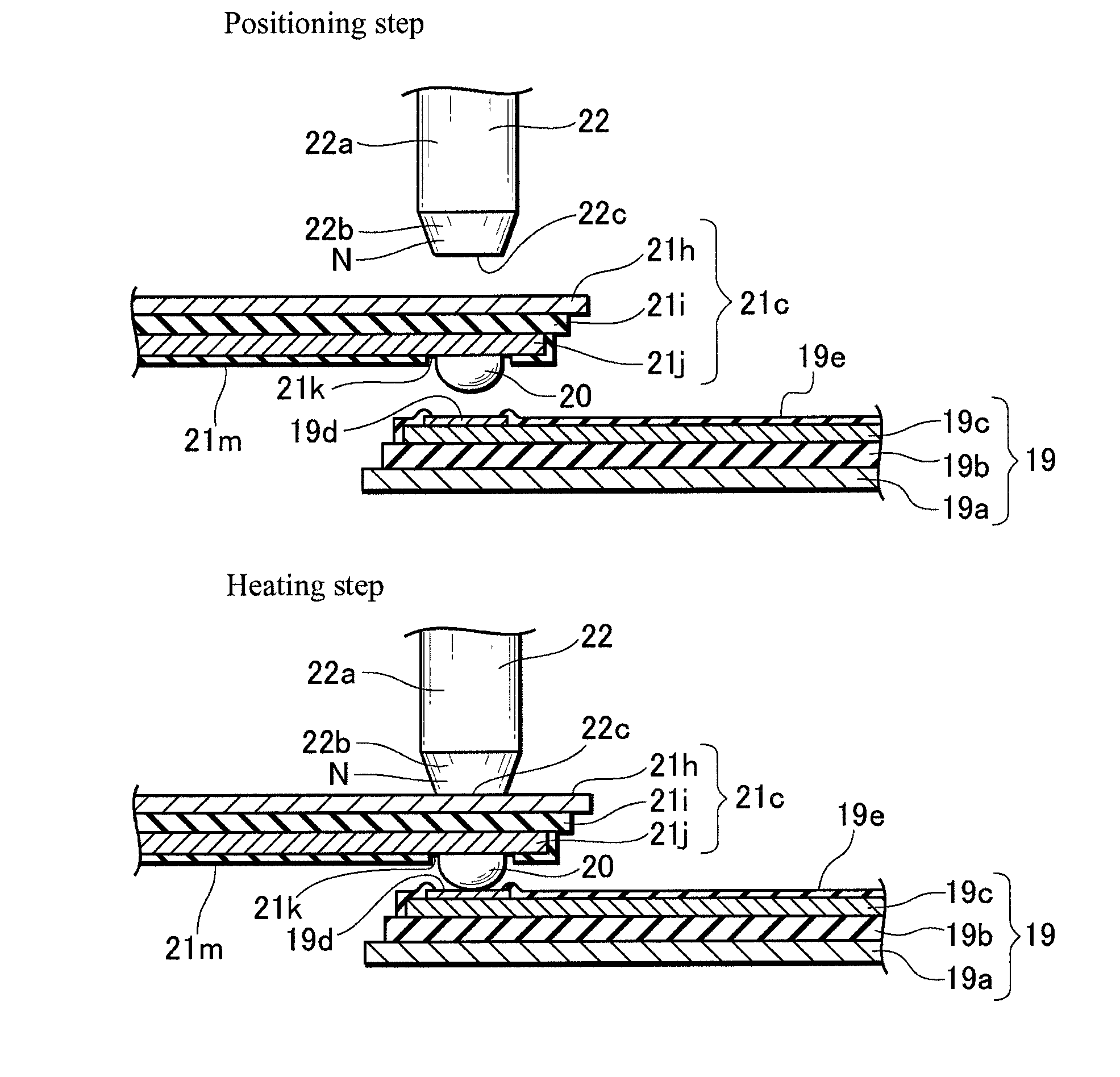
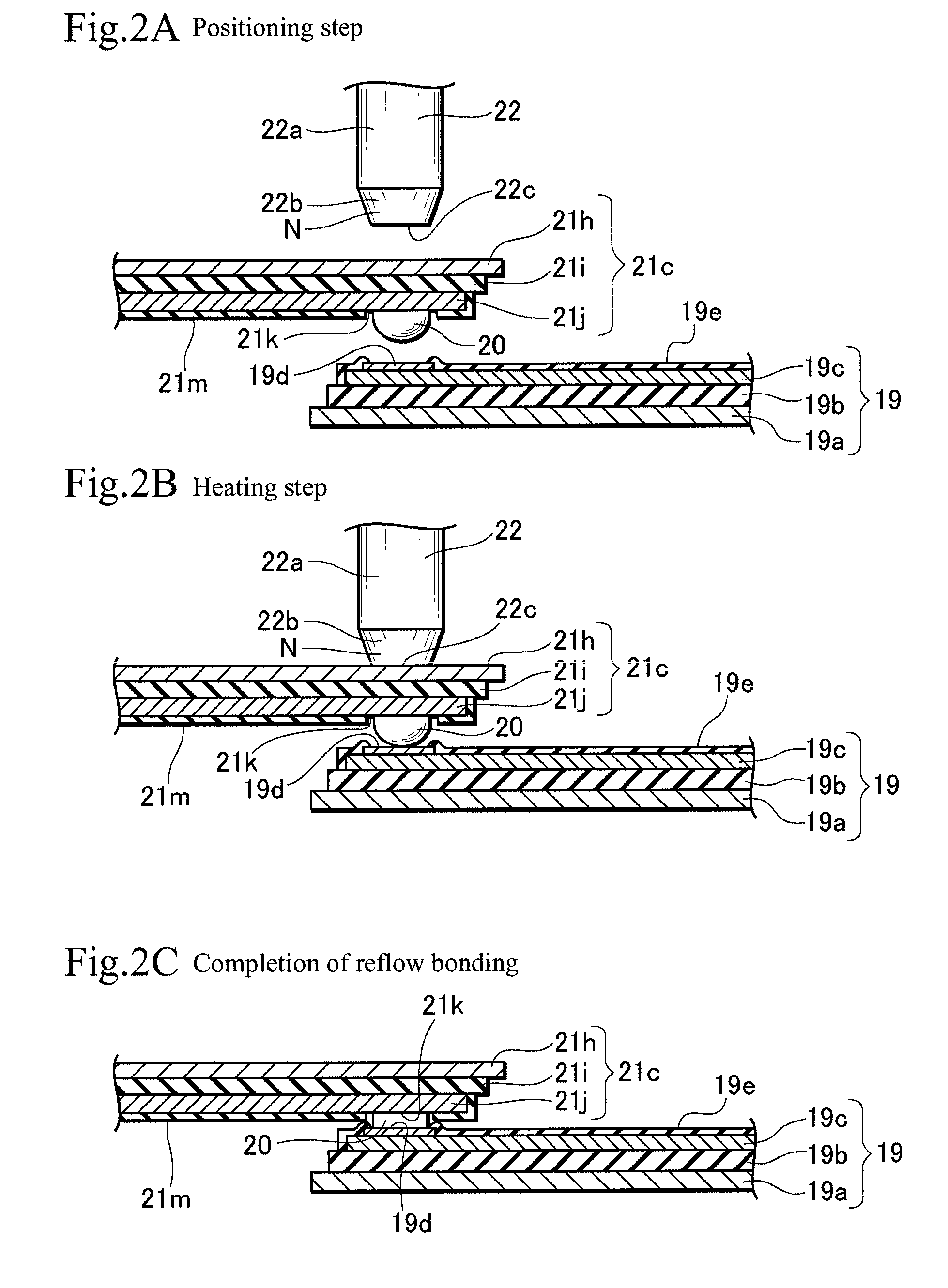
[0017]A reflow bonding method and a method of manufacturing a head suspension according to embodiments of the present invention will be explained with reference to the drawings. The reflow bonding method according to the present invention easily carries out the reflow bonding of first and second wiring members by positioning the first and second wiring members so that first and second bonding parts of the first and second wiring members face each other with solder interposed between them and by heating and pressing one of the first and second bonding parts from behind with a heater chip having a pressing face coated with a nickel film.

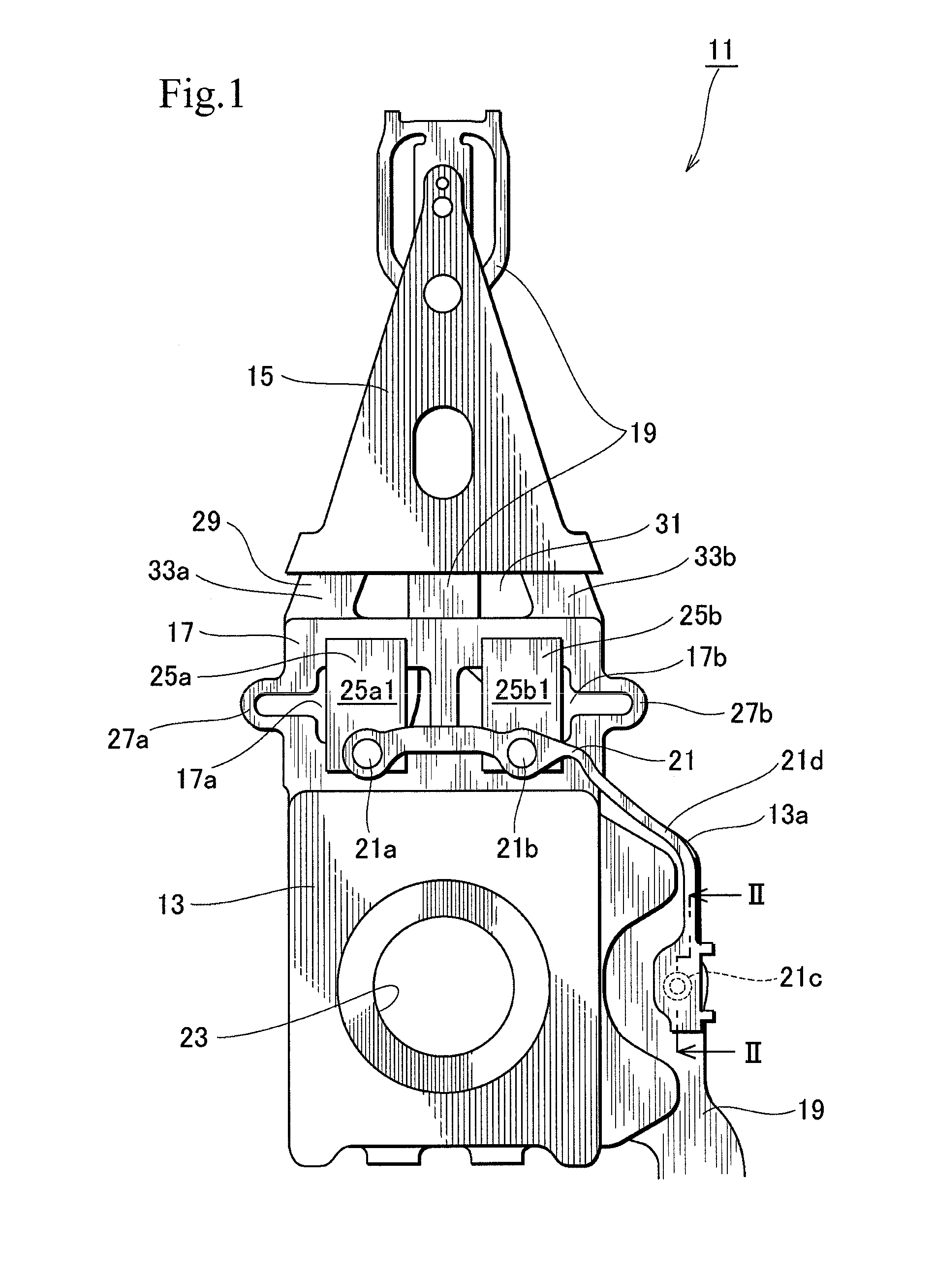
[0018]First, the head suspension to be manufactured according to the present invention will be explained. FIG. 1 is a plan view illustrating the head suspension 11 and FIGS. 2A to 2C are sectional views taken along a line II-II of FIG. 1, illustrating the head suspension 11 during the reflow bonding method of the present invention. FIG. 2A illustrates ...


PUM

PropertyMeasurementUnit
thicknessaaaaaaaaaa
thicknessaaaaaaaaaa
thicknessaaaaaaaaaa

Abstract

A reflow bonding method easily bonds first and second wiring members together by reflowing solder arranged on at least one of first and second bonding parts that are defined on the first and second wiring members, respectively. The method includes positioning the first and second wiring members so that the first and second bonding parts face each other with the solder interposed between them and heating and pressing one of the first and second bonding parts from behind with a pressing face of a heater chip so that the first and second bonding parts lie one on another and so that the solder is heated and reflows to bond the first and second wiring members together.

Description

BACKGROUND OF THE INVENTION[0001]1. Field of the Invention[0002]The present invention relates to a method of easily jointing wiring members together by reflow bonding and a method of manufacturing a head suspension with the use of the reflow bonding.[0003]2. Description of Related Art[0004]The reflow bonding employs, for example, solder to join parts such as electronic wiring members together.[0005]The reflow bonding is carried out by arranging a first wiring member plated with solder, laying a second wiring member on the first wiring member, melting the plated solder with heat, and solidifying the molten solder to bond the first and second wiring members together.[0006]Heat used for the reflow bonding may be radiant heat radiated from a high-temperature furnace as disclosed in Japanese Unexamined Patent Application Publication No. 2009-10300, Joule heat generated by passing a current to a heater chip as disclosed in Japanese Unexamined Patent Application Publication No. 2006-315043...

Claims


Application Information

Patent Timeline
Patent Type & Authority Patents(United States)
IPC IPC(8): B23K31/02
CPCB23K1/0016G11B5/4833B23K3/04
Inventor OGAKI, SHOGOANDO, TAKASHIINOUE, MASARU
Owner NHK SPRING CO LTD
Why Eureka
Try Eureka