Ground clamp

a clamping and ground technology, applied in the field of clamps, can solve the problems of cumbersome and time-consuming use of the clamping device, and achieve the effect of quick and easy alignment, quick and easy adjustmen

Active Publication Date: 2012-11-27
HALEXSCOTT FETZER
View PDF16 Cites 36 Cited by
  • Summary
  • Abstract
  • Description
  • Claims
  • Application Information

AI Technical Summary

Benefits of technology

[0011]One advantage of this invention is that the clamping members of a clamp can be quickly and easily aligned.
[0012]Another advantage of this invention is that the clamping members of a clamp can be quickly and easily adjusted to accommodate objects of differing sizes.

Problems solved by technology

While many known ground clamps work well for their intended purposes, their use can be cumbersome and time consuming.

Method used


Image

  • Ground clamp
  • Ground clamp
  • Ground clamp

Examples


Embodiment Construction

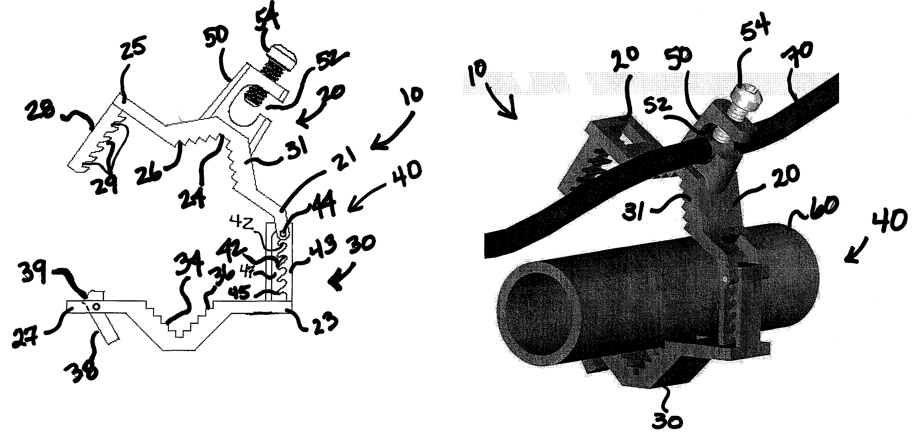
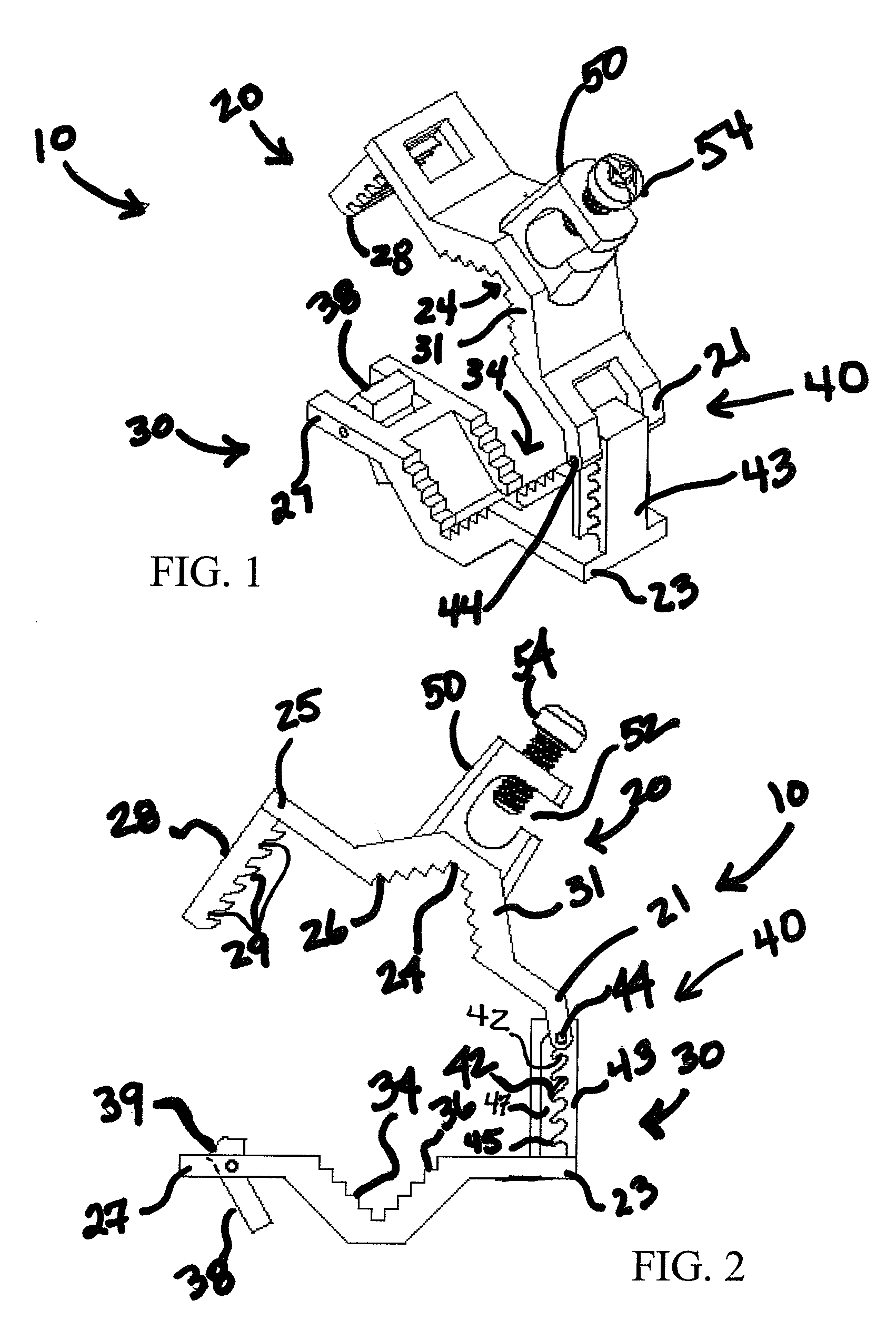
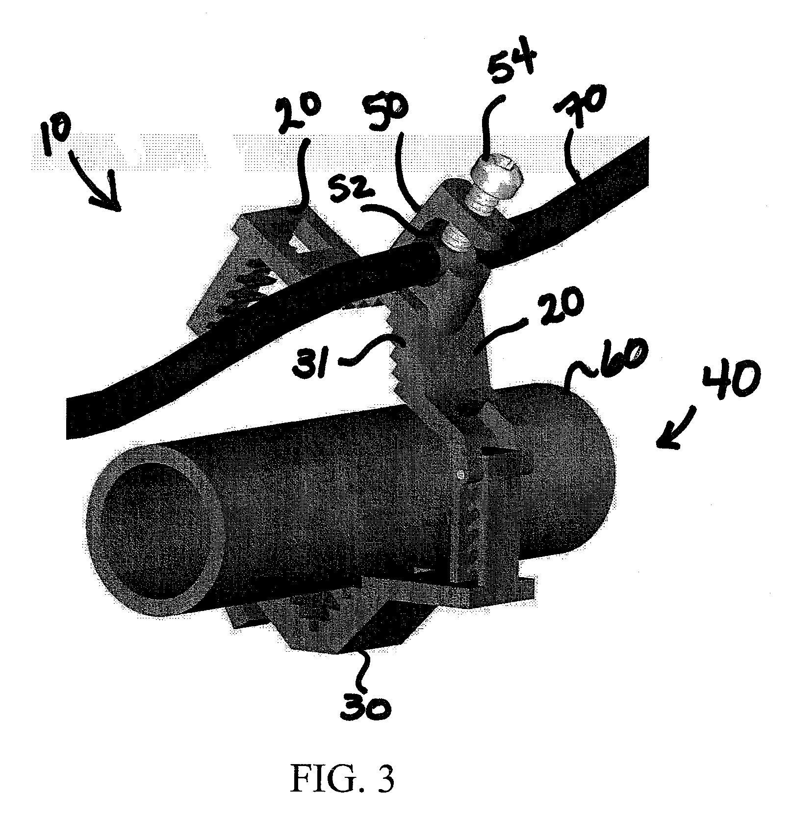
[0025]Referring now to the drawings wherein the showings are for purposes of illustrating embodiments of the invention only and not for purposes of limiting the same, and wherein like reference numerals are understood to refer to like components, FIGS. 1-8 show clamps 10, 10a that may be used in joining in electrical communication a first object 60 that is in physical contact with the ground (including but not limited to a ground rod, pipe, and rebar) with a second object 70 (including but not limited to a ground wire). In this way the ground wire is “grounded” as is well known to those of skill in the art so further details will not be provided here. When used for this purposes, the clamps 10, 10a may be formed, fully or at least in part of electrically conductive material, such as, without limitation, bronze. However, the clamps 10, 10a may be used in any other application chosen with the sound judgment of a person of skill in the art.

[0026]With reference now to FIGS. 1-4, clamp 1...


PUM


Abstract

A clamp may include two clamping members that are pivotally connected at one end.

Description

[0001]This application claims priority to U.S. Ser. No. 61 / 169,157, entitled GROUND CLAMP, filed Apr. 14, 2009, which is incorporated herein by reference.I. BACKGROUND OF THE INVENTION[0002]A. Field of Invention[0003]The present invention relates to clamps, and more particularly, clamps that have a particular configuration to assist in connecting wires, conduits, rods, rebar, and in particular embodiments, ground wires, rods, and pipes.[0004]B. Description of the Related Art[0005]FIG. 9 shows a known ground clamp 500 that includes first and second clamping members 502, 504, and a retainer 506 that is connected to the first clamping member 502 and is used to secure a ground wire (not shown) to the ground clamp 500. A ground rod (not shown) is secured (clamped) between the first and second clamping members 502, 504 to thereby join in electrical communication the ground wire and the ground rod. In this way the ground wire is “grounded” as is well known to those of skill in the art.[000...

Claims


Application Information

Patent Timeline
Patent Type & Authority Patents(United States)
IPC IPC(8): H01R4/66
CPCH01R4/36H01R4/42H01R4/40F16B2/10Y10T24/4453Y10T24/44291
Inventor GARDNER, MICHAEL J.BAKER, GLENN A.
Owner HALEXSCOTT FETZER
Why Eureka
Try Eureka