Microfluidic apparatus and methods for performing blood typing and crossmatching

a microfluidic device and antibody technology, applied in the field of antigen agglutination reactions in microfluidic devices, can solve the problem of increasing the rate of agglutination

Active Publication Date: 2012-11-27
PERKINELMER HEALTH SCIENCES INC
View PDF58 Cites 52 Cited by
  • Summary
  • Abstract
  • Description
  • Claims
  • Application Information

AI Technical Summary

Benefits of technology

[0031]Under ideal conditions, the two streams flowing next to each other form a concentration gradient of antibody diffusing into the particle stream and particles or aggregates impinging against the antibody stream. Increasing the surface area or concentration gradient of this boundary increases the rate of agglutination. Agglutination results when particles such as blood cells, including erythrocytes and platelets, or latex particles, for example, are bridgingly crosslinked or otherwise aggregated by formation of antigen:antibody affinity pairs at the interfacial boundary, and appear as clumps of particles that are readily distinguishable to the eye.
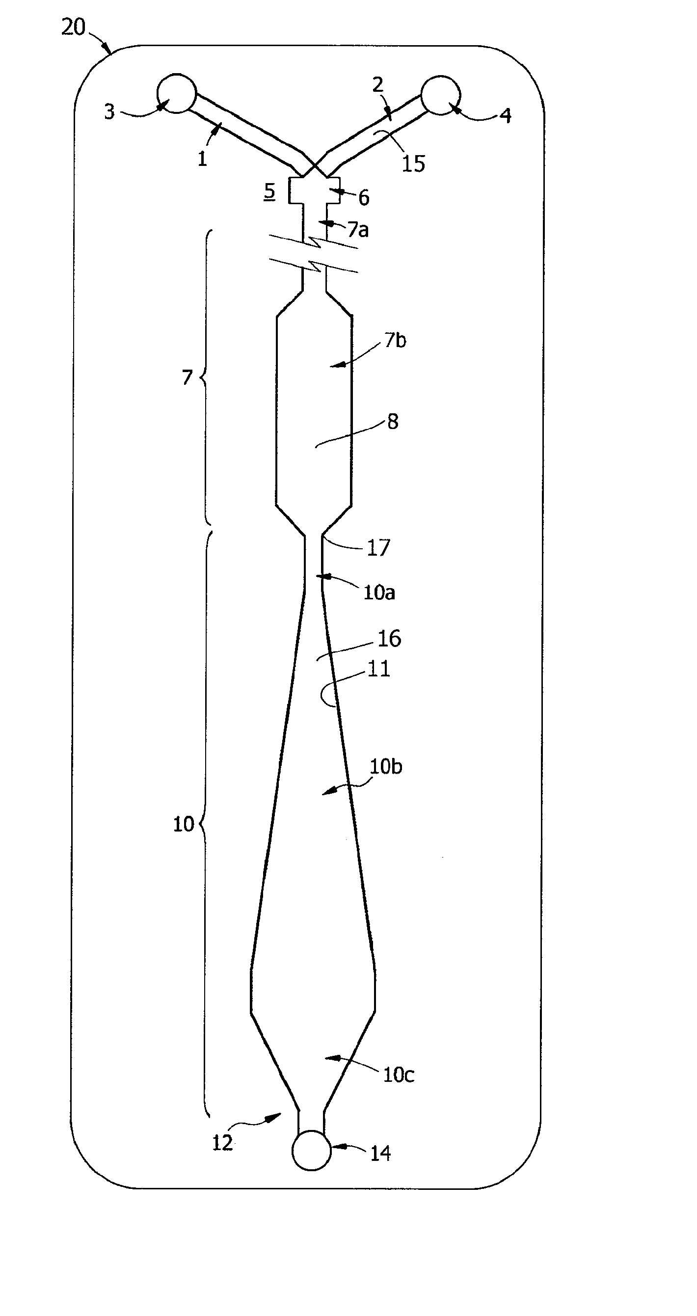
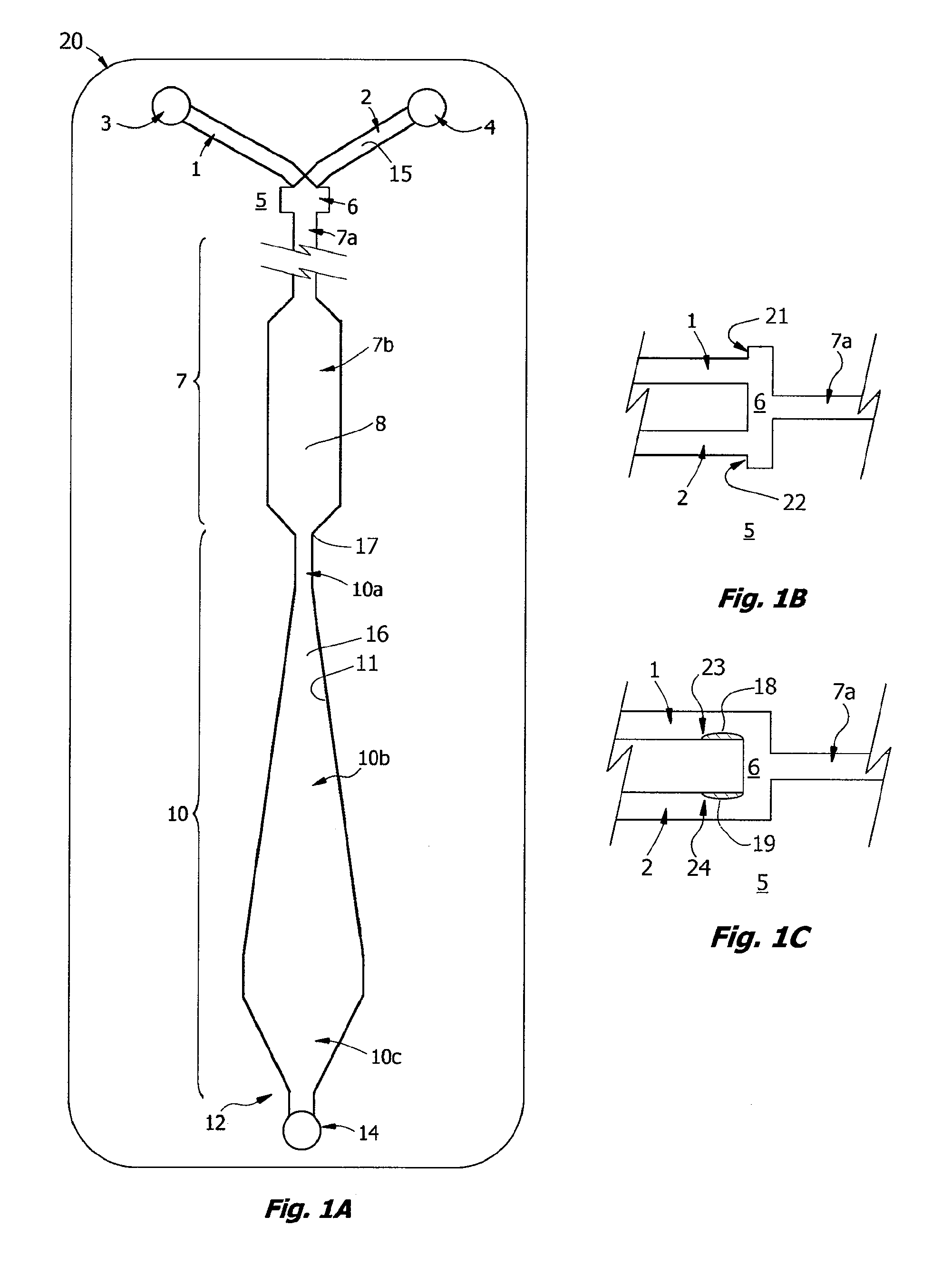
[0045]Provision for downstream flow control with prolongation of low Reynolds Number flow is found to improve agglutination of a variety of antigen:antibody systems. Thus in another aspect, the invention is a microfluidic cartridge for performing a blood type assay or crossmatch, or an agglutination reaction more generally, having a union or “tee” for contacting a first fluid and a second fluid, the first fluid containing an antigen and the second fluid containing an antibody, in which the fluids are first contacted to form two layers flowing one on top of the other (termed here a “horizontally-stratified laminar fluid diffusion interface”) in a reaction channel and then capillary flow is sustained and modulated by prolonging flow in an elongate downstream flow control channel having a microfluidic critical dimension and a reverse taper that broadens from upstream to downstream (ie. the aspect ratio of the channel increases). Generally, the microfluidic cartridge includes a) a body member composed of a substrate or substrates and having a reaction channel enclosed therein, the reaction channel having a first end and a second end and having a z-dimension configured for establishing laminar flow conditions; b) a first intake channel for conveying a first fluid and a second intake channel for conveying a second fluid to a staging union fluidly joined to the first end of the reaction channel, where the staging union is configured for synchronizing flow of the two fluids past a pair of capillary stops, one capillary stop for each intake channel; and c) a downstream flow control channel joined to the second end of the reaction channel. The downstream flow control channel is configured with broadening taper for modulating capillary flow at low Reynolds Number for a sustained period of time, and is vented downstream. The geometry, volume, and surface properties of the downstream flow control channel are optimized for each application. Optionally the downstream flow control channel can include a throat with flow constrictor for suppressing pulsatile flow in the reaction channel during initial wetting. Wetting is generally initiated by a pulse of suction pressure applied downstream, such as by a finger-operated diaphragm pump with suction stroke. Surface properties, geometry and dimensions of the channels are configured to modulate capillary flow at transitional or low Reynolds Number for a sustained period of flow during which agglutination is potentiated. An observation window provided on the reaction channel is used to detect agglutination. The downstream flow control channel is terminated in a vent or check valve.

Problems solved by technology

Increasing the surface area or concentration gradient of this boundary increases the rate of agglutination.

Method used


Image

  • Microfluidic apparatus and methods for performing blood typing and crossmatching
  • Microfluidic apparatus and methods for performing blood typing and crossmatching
  • Microfluidic apparatus and methods for performing blood typing and crossmatching

Examples


example 1

Blood Typing

[0223]A prototype of the ABO / Rh cartridges of the invention, essentially the cartridge of FIG. 9, was fabricated by lamination and tested in a clinical trial. Each disposable cartridge contained three separate reaction channels and all on-board reagents testing a blood specimen for A, B and D antigens. Blood collected with EDTA or citrate was first tested by a reference laboratory and then by ABO and Rh typing with the prototype design. For the testing protocol, the cartridge was first placed on a flat surface and an on-card foil reagent pouch containing rehydration buffer was ruptured so that all three reagent inlet lines, each of which contained a dried antiserum in a rapid rehydration matrix, were filled. The volume of buffer used in the test was about 80 μL and a sample of 30 μL blood was used for each test. Blood was added in the sample well and allowed to fill the sample distribution manifold so that all three channels were primed. Both reagent and blood filled the...

example 2

Weak Agglutinins

[0226]Known “weak A” specimens and known “weak D” blood samples were tested by the protocol of Example 1, the ABO / Rh Card was able to correctly type 2 of 4 weak D samples and 2 of 3 weak A samples within 60 sec and without 37° C. incubation.

[0227]For blood typing with Anti-D antibody, linear velocities in the reaction window of less than about 0.2 mm / s, corresponding to a Reynolds Number Re of about 0.01 for blood, were found not to be useful. Reynolds Numbers in the range of 0.1 to 1.0 for blood are associated with agglutination in less than 30 seconds. These Reynolds Numbers correspond to linear velocities in the range of 2 to 20 mm / s, most preferably in the range of 2.5 to 5 mm / s. These numbers roughly correspond to what is termed here transitional or “near-creeping flow” where Re<10 or perhaps in the transition range from creeping flow to laminar flow, depending on the viscosity. At lower viscosity, such as for water, these velocities correspond to Reynolds Numbe...

example 3

Inverted Cartridge Test

[0229]Rehydration buffer and blood sample were primed in a cartridge as described in Example 1 and the cartridge was inverted face down before being placed flat on a table. By sliding the device so that it was partially placed over the edge of the table, the diaphragm pump could be accessed and the assay initiated, essentially following the protocol of Example 1. The assay resulted in the correct blood type being determined within 60 sec. Unexpectedly, this indicates that the HLFD interface reaction between blood and antibody of the present invention is not dependent on gravitational settling of the erythrocytes as described by Klein in U.S. Pat. No. 6,488,896.


PUM

PropertyMeasurementUnit
Reynolds Numberaaaaaaaaaa
contact angleaaaaaaaaaa

Abstract

Microfluidic cartridges for agglutination reactions are provided. The cartridges include a microfluidic reaction channel with at least two intake channels, one for an antigen-containing fluid and the other for an antibody-containing fluid, conjoined to a reaction channel modified by incorporation of a downstream flow control channel. At low Reynolds Number, the two input streams layer one on top of the other in the reaction channel and form a flowing, unmixed horizontally-stratified laminar fluid diffusion (HLFD) interface for an extended duration of reaction. Surprisingly, the design, surface properties, and flow regime of microfluidic circuits of the present invention potentiate detection of antibody mediated agglutination at the stratified interface. Antigen:antibody reactions involving agglutination potentiated by these devices are useful in blood typing, in crossmatching for blood transfusion, and in immunodiagnostic agglutination assays, for example.

Description

CROSS-REFERENCE TO RELATED APPLICATIONS[0001]This application claims the benefit under 35 U.S.C. §119(e) of U.S. Provisional Patent application Ser. No. 61 / 102,694, filed on Oct. 3, 2008, and U.S. Provisional Patent application Ser. No. 61 / 228,700, filed Jul. 27, 2009, which applications are incorporated herein by reference in their entireties.BACKGROUND[0002]1. Field[0003]This invention pertains to devices, apparatus, and methods for potentiation of agglutination reactions and more generally to antigen:antibody reactions in microfluidic devices. Antigen:antibody reactions involving agglutination are useful in blood typing, in crossmatching for blood transfusion, and in immunodiagnostic agglutination assays in general.[0004]2. Description of Related Art[0005]Administration of blood in the form of packed erythrocytes or whole blood is often useful in the treatment of trauma, hypovolemic shock, anemia and clotting disorders, and generally requires, at a minimum, characterization of th...

Claims


Application Information

Patent Timeline
Patent Type & Authority Patents(United States)
IPC IPC(8): G01N33/53
CPCB01L3/502776G01N33/80G01N33/5304B01L3/502761B01L2200/0636B01L2300/0887B01L2300/161B01L2300/0816G01N33/53B01L3/502715B01L3/50273B01L3/502738B01L3/502746B01L2300/0627B01L2300/0867
Inventor BATTRELL, C. FREDERICKWIERZBICKI, DIANECLEMMENS, JOHNCAPODANNO, JASONWILLIFORD, JOHN R.ELMUFDI, CAROLINASPRAGUE, ISAAC
Owner PERKINELMER HEALTH SCIENCES INC
Why Eureka
Try Eureka