Optical image monitoring system and method for vehicles

a technology of optical image and monitoring system, applied in the field of optical feature recognition, can solve the problems of large storage space for video data stored on board the vehicle, inability to meet the requirements of vehicle camera system use,

Active Publication Date: 2012-11-27
APPAREO SYST
View PDF35 Cites 108 Cited by
  • Summary
  • Abstract
  • Description
  • Claims
  • Application Information

AI Technical Summary

Problems solved by technology

Systems attempting to recognize handwritten text have the added challenge of handling the variations in personal handwriting styles from one person to the next.
Storing the video data on board the vehicle requires a large amount of storage space.
The external image data thus captured is subject to the same storage and quality limitations inherent in the storage of image data from the interior of the vehicle.
Commercially available camera systems for use in vehicles do not perform well in these conditions, and provide low-quality images.
These limitations make the task of post-processing the image data to clearly identify details within the images difficult if not impossible.

Method used


Image

  • Optical image monitoring system and method for vehicles
  • Optical image monitoring system and method for vehicles
  • Optical image monitoring system and method for vehicles

Examples


Embodiment Construction

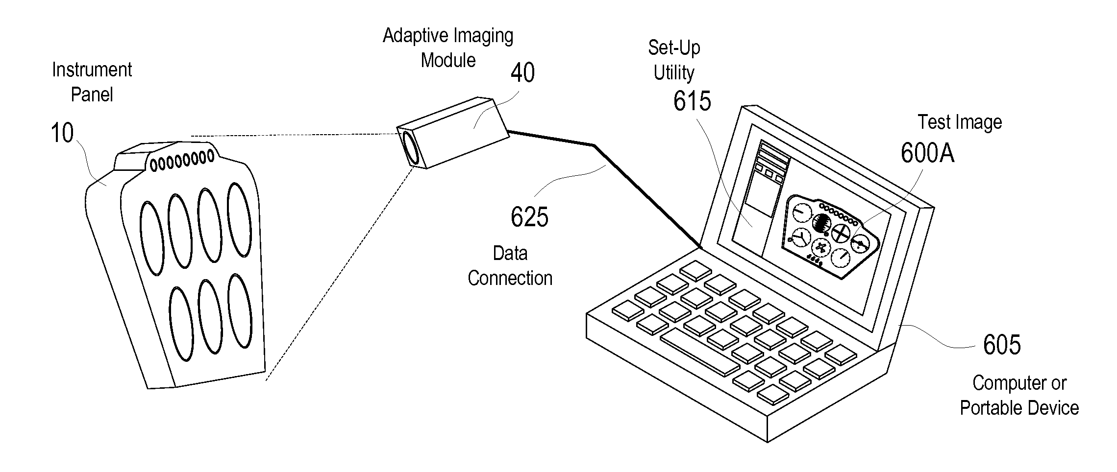
[0036]With reference now to the drawings, and in particular to FIGS. 1 through 12 thereof, a new adaptive feature recognition process and device embodying the principles and concepts of the present invention will be described.

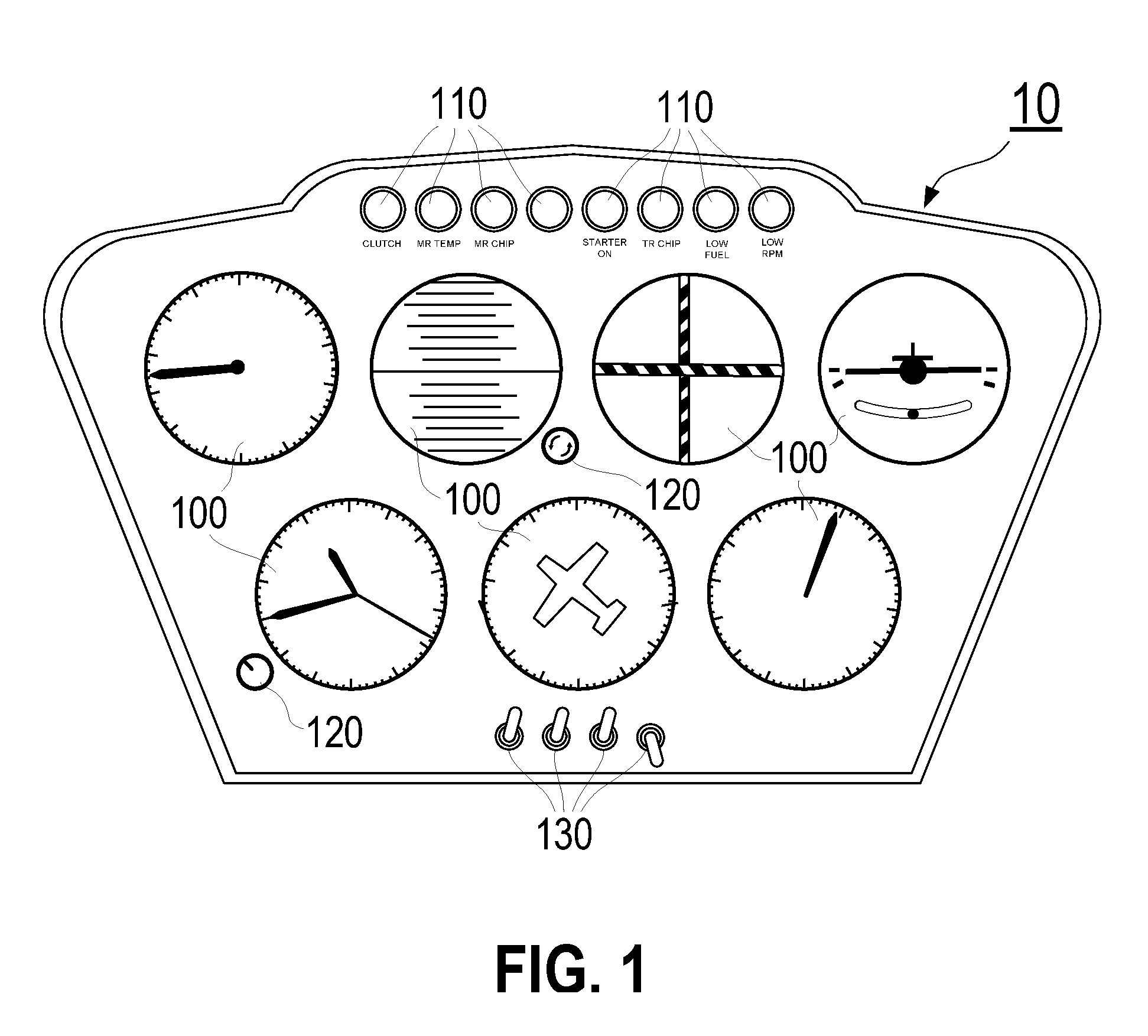
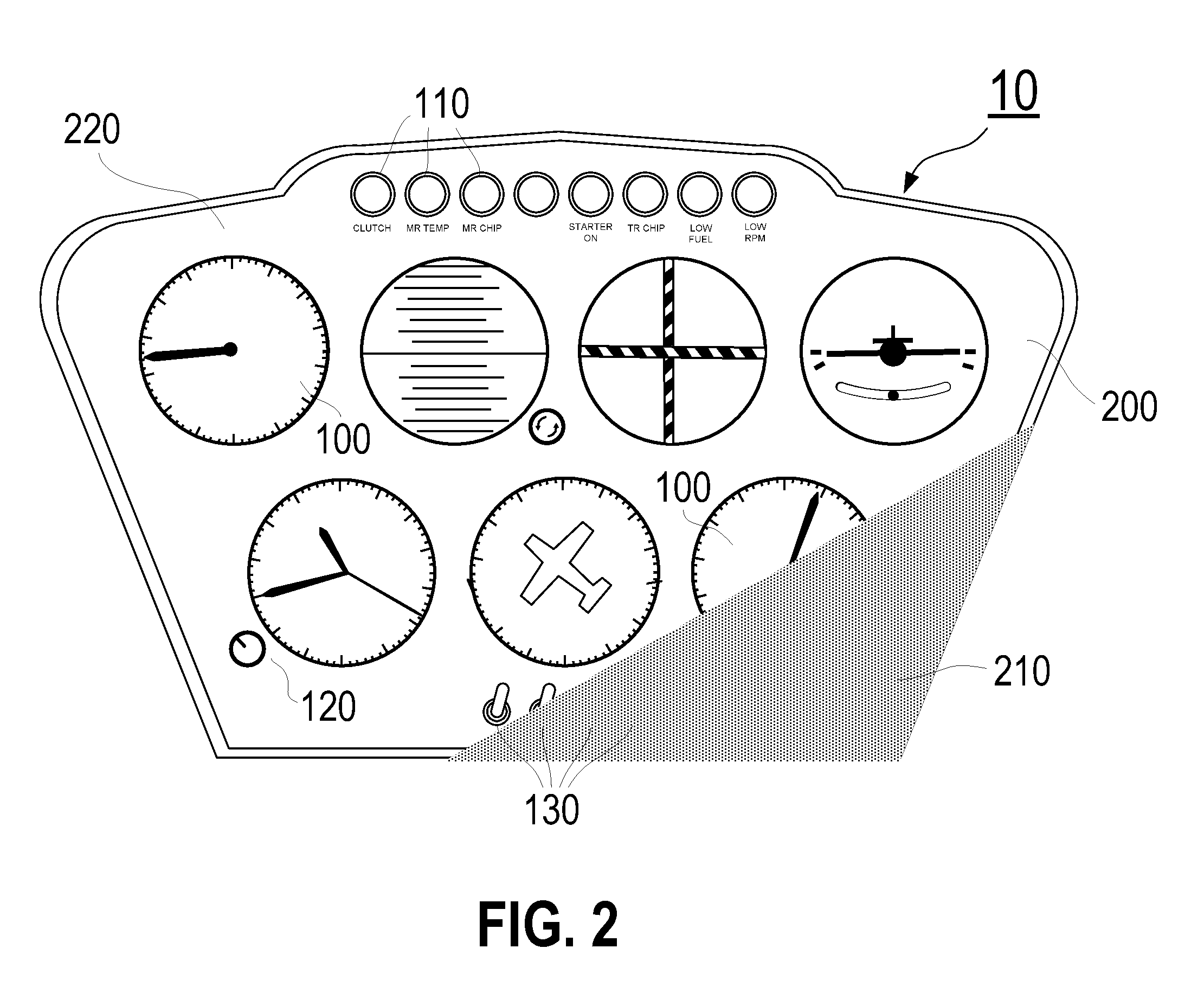
[0037]FIG. 1 is a front view of a representative instrument panel 10. For the purposes of this discussion, an “instrument panel” shall be defined as a fixed arrangement of gauges, lights, digital readouts, displays, and user controls as might be seen in the cab of a vehicle, such as a car or truck, or in the cockpit of an aircraft. The depiction of the instrument panel 10 in FIG. 1 is meant to be illustrative of the type and style of features as might be seen in any type of vehicle, and not meant to be limiting in any way. The features shown in FIG. 1 are suggestive of those that might be seen on an aircraft such as a helicopter, but the present invention will work equally well on any type of instruments in any type of vehicle. In addition, for the purposes of ...


PUM


Abstract

A system and method of acquiring information from an image of a vehicle in real time wherein at least one imaging device with advanced light metering capabilities is placed aboard a vehicle, a computer processor means is provided to control the imaging device and the advanced light metering capabilities, the advanced light metering capabilities are used to capture an image of at least a portion of the vehicle, and image recognition algorithms are used to identify the current state or position of the corresponding portion of the vehicle.

Description

CROSS-REFERENCE TO RELATED APPLICATION[0001]This application is a continuation-in-part of and claims the benefit of U.S. patent application Ser. No. 12 / 390,146, filed Feb. 20, 2009, which is incorporated herein by reference.BACKGROUND OF THE INVENTION[0002]1. Field of the Invention[0003]This invention relates to the field of optical feature recognition, and more particularly to a system and method for automatically interpreting and analyzing gauges, readouts, the position and state of user controls, and the exterior of a vehicle, such as an aircraft, including the position and state of flight control surfaces, in an environment with highly dynamic lighting conditions.[0004]2. Description of the Related Art[0005]The recording and automated analysis of image data is well known in the prior art. For example, optical character recognition, or OCR, is the process of analyzing an image of a document and converting the printed text found therein into machine-editable text. OCR programs are...

Claims


Application Information

Patent Timeline
Patent Type & Authority Patents(United States)
IPC IPC(8): G08B21/00G06V20/59
CPCB64D45/00G06K9/00G07C5/0891G06F17/00G07C5/0866G06K2209/03G06V2201/02G06V20/59G06F18/00
Inventor WEINMANN, ROBERT V.GELINSKE, JOSHUA N.ALLEN, ROBERT M.WIIG, JOHAN A.
Owner APPAREO SYST
Why Eureka
Try Eureka