Magnetic head assembly and magnetic recording/reproducing apparatus

a head assembly and magnetic recording technology, applied in the field of magnetic recording heads, can solve the problems of large change in the oscillation characteristics of the spin torque oscillator, the difficulty of achieving such high recording density, and the temporary decrease in the recording density

Active Publication Date: 2012-11-27
KK TOSHIBA
View PDF153 Cites 70 Cited by
  • Summary
  • Abstract
  • Description
  • Claims
  • Application Information

AI Technical Summary

Benefits of technology

[0012]The present invention has been made in view of these circumstances, and an object thereof is to provide a magnetic recording head for high-frequency field assist recording that can reduce the write magnetic field generated from the main magnetic pole toward the spin torque oscillator, and a magnetic recording apparatus that uses the magnetic recording head.

Problems solved by technology

However, the recording density increase rate temporarily became lower in the beginning of the 2000's, since the problem of heat fluctuations of magnetic recording media rose up to the surface.
However, achieving such high recording density is considered not easy even by a vertical magnetic recording method, as the problem of heat fluctuations will surface again.
As a result, the oscillation characteristics of the spin torque oscillator are greatly changed with the change in the write magnetic field generated from the main magnetic field, and it becomes difficult to generate a stable high-frequency magnetic field.
As will be described later, due to the magnetic field generated from the main magnetic pole, the oscillation frequency of the spin torque oscillator and the current density required for oscillation are increased, and it becomes difficult to maintain the reliability of the spin torque oscillator.

Method used


Image

  • Magnetic head assembly and magnetic recording/reproducing apparatus
  • Magnetic head assembly and magnetic recording/reproducing apparatus
  • Magnetic head assembly and magnetic recording/reproducing apparatus

Examples


first embodiment

(First Embodiment)

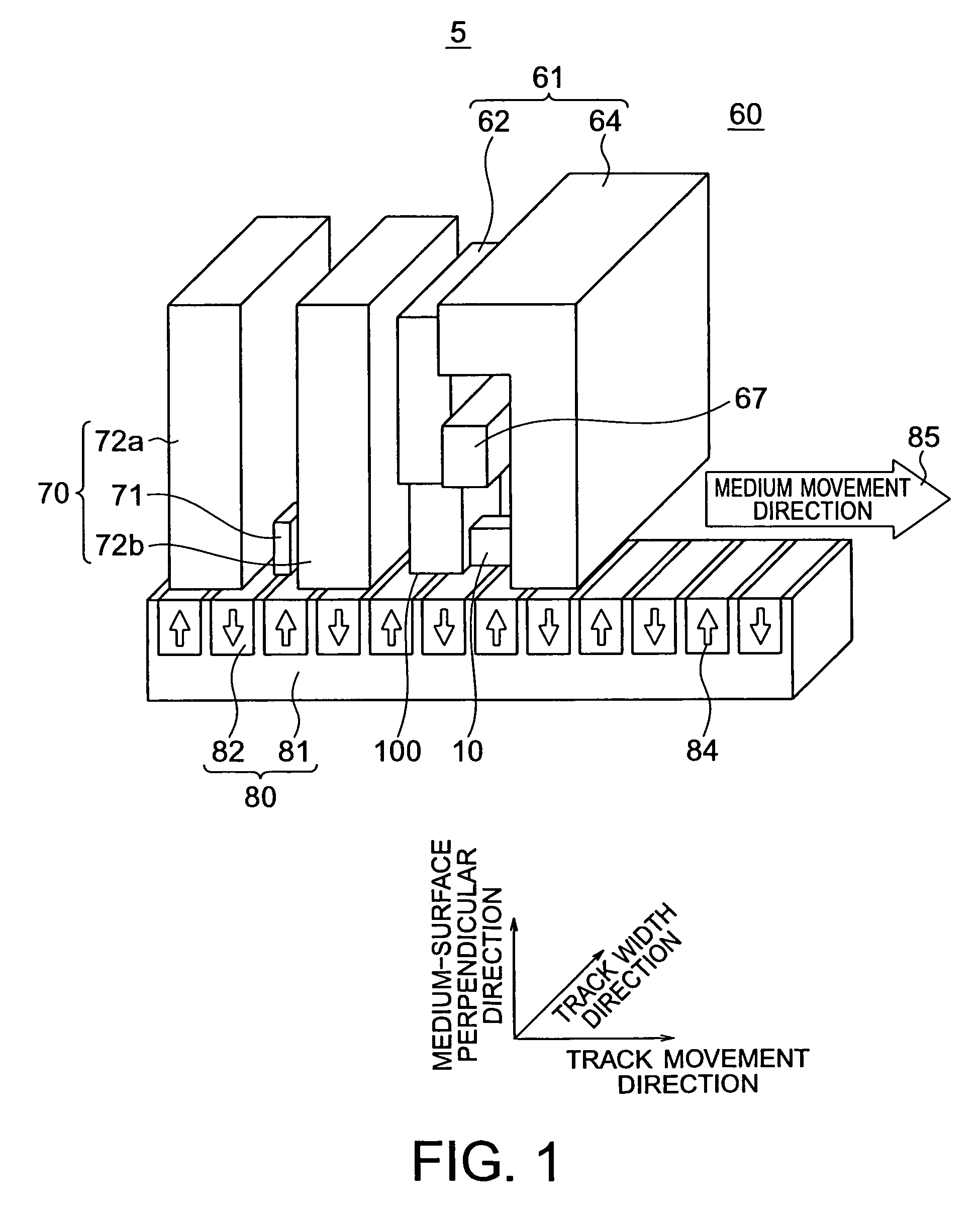
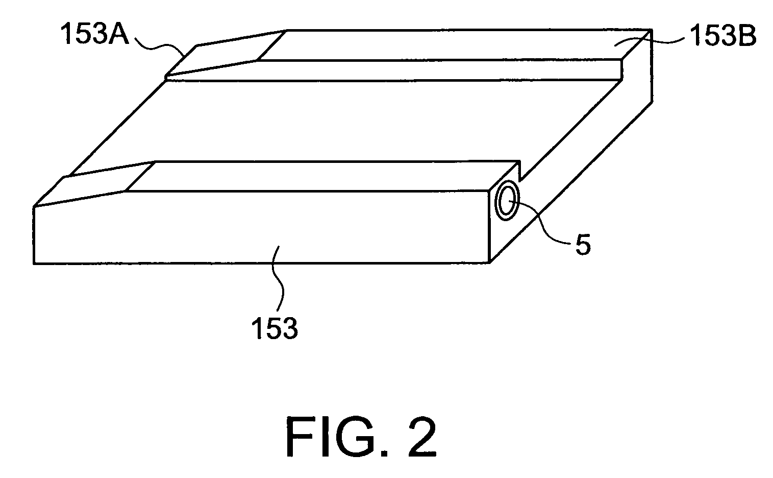
[0035]Referring to FIGS. 1 through 5, a magnetic recording head for high-frequency field assist recording in accordance with a first embodiment of the present invention is described. FIG. 1 is a schematic perspective view showing the structure of the magnetic recording head 5 of this embodiment. FIG. 2 is a perspective view of a head slider 153 on which the magnetic recording head 5 is mounted. FIG. 3 is a perspective view of a head stack assembly 160 on which the head slider 153 is mounted, seen from the side of a magnetic recording medium 80. FIG. 4 is a perspective view showing the arrangement of a spin torque oscillator 10 and sidewall magnetic layers 101 that are provided in the magnetic recording head 5 of this embodiment. FIG. 5 is a plan view of the magnetic recording head 5, seen from the side of the magnetic recording medium 80.

[0036]The magnetic recording head 5 of this embodiment includes a writing head unit 60 and a reproducing head unit 70. The reprod...

second embodiment

(Second Embodiment)

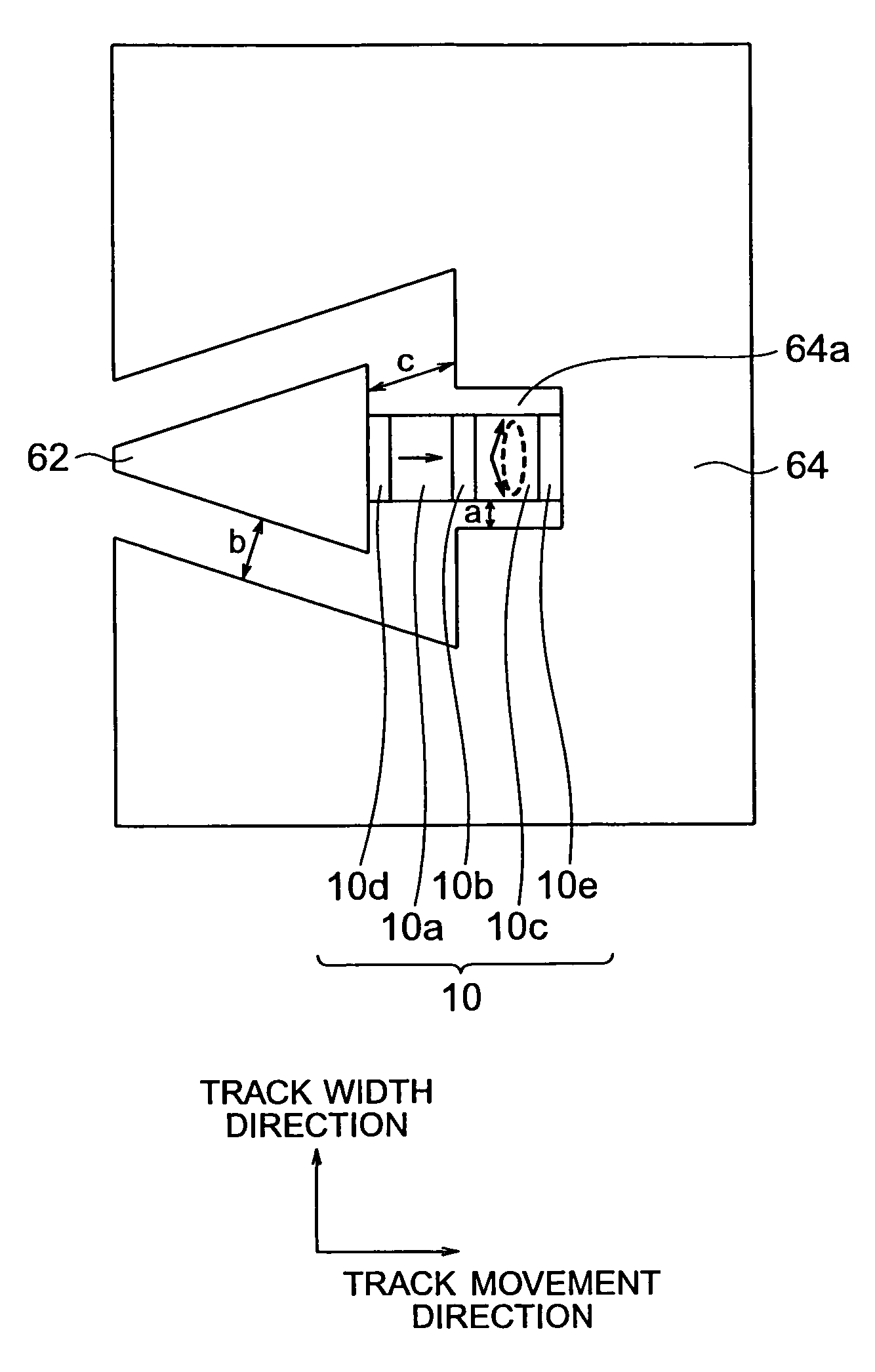
[0062]Referring now to FIG. 8, a magnetic recording head in accordance with a second embodiment of the present invention is described. FIG. 8 is a plan view of the magnetic recording head of this embodiment, seen from the medium-facing surface.

[0063]This embodiment differs from the first embodiment in that the sidewall magnetic layers 101 are replaced with the magnetic shield 64. More specifically, the magnetic shield 64 is placed in the vicinities of the track width direction sides of the main magnetic pole 62 and the spin torque oscillator 10. In this embodiment, at least the oscillation layer 10c and the nonmagnetic layer 10e among the layers of the spin torque oscillator 10 are located within a concave portion 64a formed in the magnetic shield 64, as shown in FIG. 8. In this case, the nonmagnetic layer 10e is in contact with the bottom face of the concave portion 64a. Although an example case where the magnetic shield 64 is placed in the vicinities of and face...

third embodiment

(Third Embodiment)

[0070]Next, a magnetic recording / reproducing apparatus in accordance with a third embodiment of the present invention is described. The magnetic recording head of any of the embodiments and modifications illustrated in FIGS. 1 through 11 can be incorporated into a head stack assembly of a recording / reproducing type, and can be mounted on a magnetic recording / reproducing apparatus. The magnetic recording / reproducing apparatus of this embodiment includes: a magnetic recording medium; the magnetic recording head of one of the above embodiments; a movement control unit that controls the magnetic recording medium and the magnetic recording head to have relative movements in a floating or contact state, the magnetic recording medium and the magnetic head assembly facing each other; a position control unit that controls the magnetic recording head to be located in a predetermined recording position on the magnetic recording medium; and a signal processing unit that perfor...


PUM

PropertyMeasurementUnit
oscillation frequencyaaaaaaaaaa
thicknessaaaaaaaaaa
thicknessaaaaaaaaaa

Abstract

It is made possible to reduce the write magnetic field generated from the main magnetic pole toward the spin torque oscillator, so as to reduce the variation in the oscillation characteristics of the spin torque oscillator, and reduce the current required for oscillation. The magnetic head assembly includes: a recording magnetic pole; a spin torque oscillator that has first and second magnetic layers, and an intermediate layer interposed between the first and second magnetic layers, the spin torque oscillator generating a high-frequency magnetic field by applying a current between the first and second magnetic layers; and a third magnetic layer that is placed adjacent to at least part of a side face of the second magnetic layer.

Description

CROSS-REFERENCE TO RELATED APPLICATION[0001]This application is based upon and claims the benefit of priority from prior Japanese Patent Application No. 2008-160856 filed on Jun. 19, 2008 in Japan, the entire contents of which are incorporated herein by reference.BACKGROUND OF THE INVENTION[0002]1. Field of the Invention[0003]The present invention relates to a magnetic recording head that has a spin torque oscillator suitable for data storage of high recording density, high recording capacity, and a high data transfer rate. The present invention also relates to a magnetic head assembly and a magnetic recording / reproducing apparatus.[0004]2. Related Art[0005]In 1990's, there were dramatic increases in recording density and recording capacity of an HDD (hard disk drive), as MR (Magneto-Resistive effect) heads and GMR (Giant Magneto-Resistive effect) heads were put into practical use. However, the recording density increase rate temporarily became lower in the beginning of the 2000's, ...

Claims


Application Information

Patent Timeline
Patent Type & Authority Patents(United States)
IPC IPC(8): G11B5/127G11B5/187
CPCB82Y25/00G11B5/3906B82Y10/00G11B2005/3996G11B2005/0005
Inventor IWASAKI, HITOSHIYAMADA, KENICHIROTAKAGISHI, MASAYUKIFUNAYAMA, TOMOMITAKASHITA, MASAHIROSHIMIZU, MARIKOOIKAWA, SOICHIKOUI, KATSUHIKO
Owner KK TOSHIBA
Why Eureka
Try Eureka