Magnetic head assembly and magnetic recording/reproducing apparatus
a head assembly and magnetic recording technology, applied in the field of magnetic recording heads, can solve the problems of large change in oscillation characteristics of spin torque oscillators, low recording density increase rate, and difficulty in achieving such high recording density
- Summary
- Abstract
- Description
- Claims
- Application Information
AI Technical Summary
Benefits of technology
Problems solved by technology
Method used
Image
Examples
first embodiment
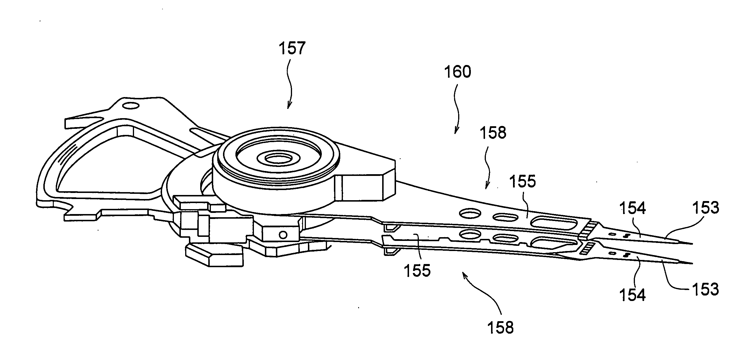
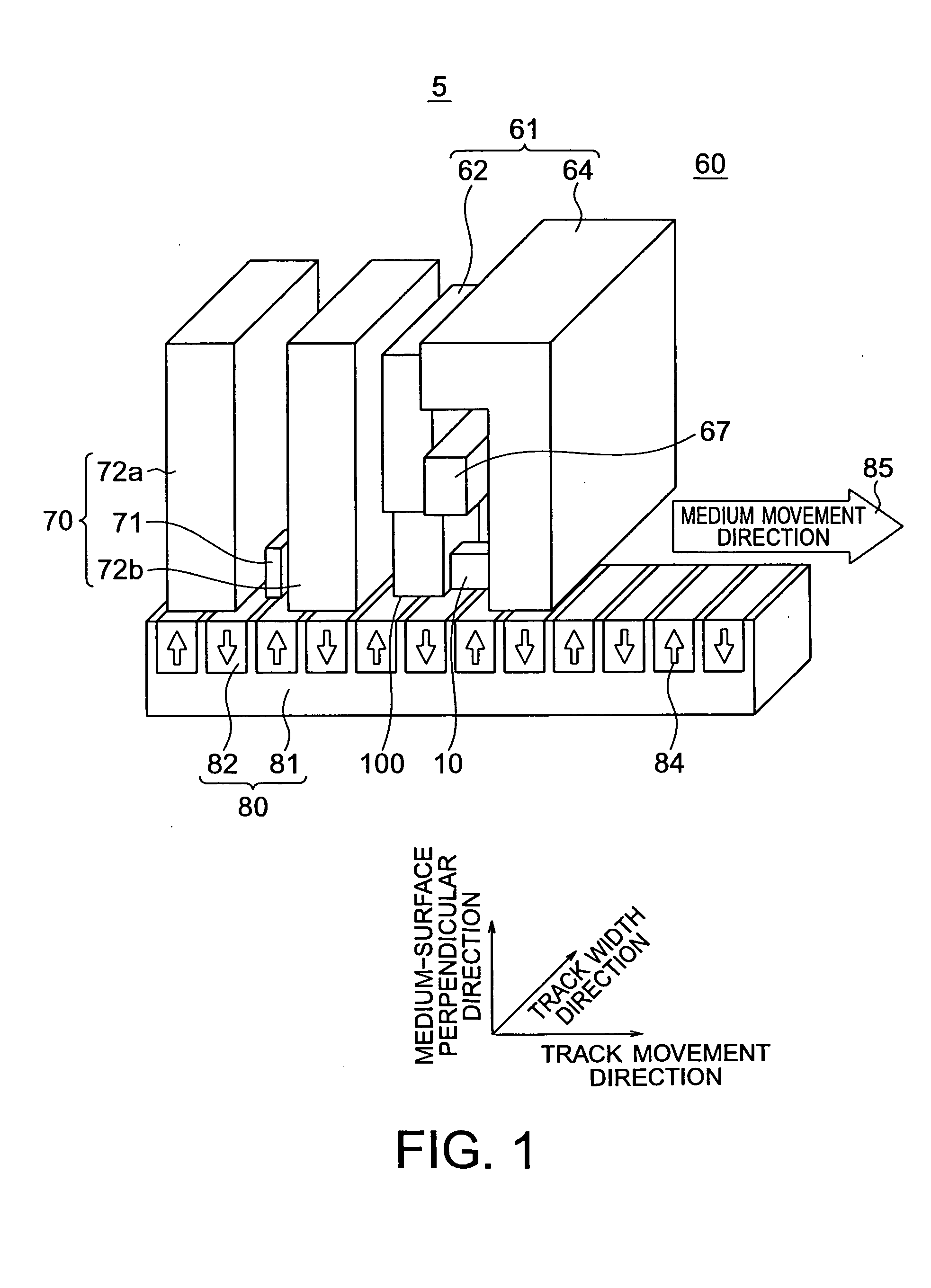
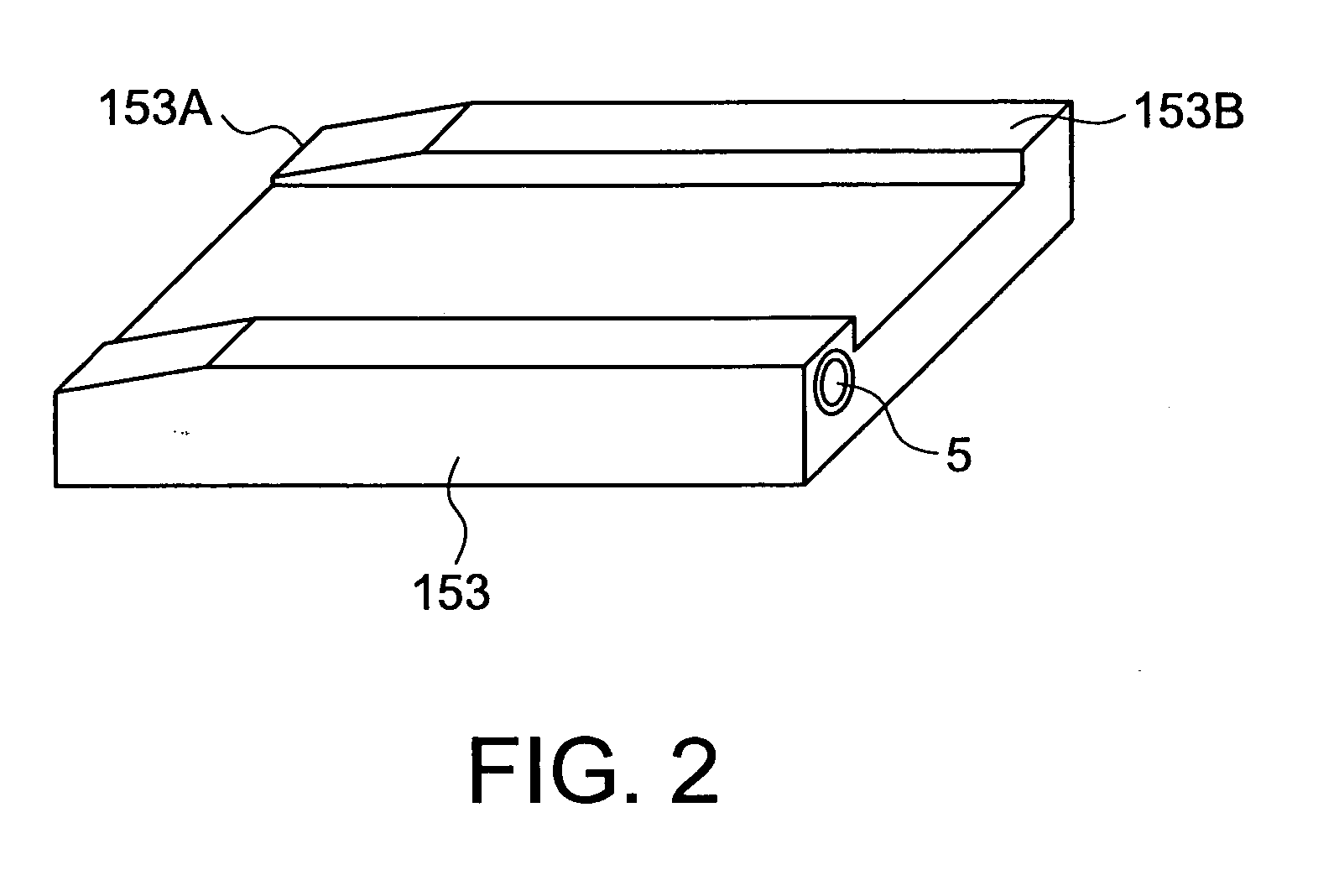
[0035]Referring to FIGS. 1 through 5, a magnetic recording head for high-frequency field assist recording in accordance with a first embodiment of the present invention is described. FIG. 1 is a schematic perspective view showing the structure of the magnetic recording head 5 of this embodiment. FIG. 2 is a perspective view of a head slider 153 on which the magnetic recording head 5 is mounted. FIG. 3 is a perspective view of a head stack assembly 160 on which the head slider 153 is mounted, seen from the side of a magnetic recording medium 80. FIG. 4 is a perspective view showing the arrangement of a spin torque oscillator 10 and sidewall magnetic layers 101 that are provided in the magnetic recording head 5 of this embodiment. FIG. 5 is a plan view of the magnetic recording head 5, seen from the side of the magnetic recording medium 80.
[0036]The magnetic recording head 5 of this embodiment includes a writing head unit 60 and a reproducing head unit 70. The reproducing head unit 70...
second embodiment
[0062]Referring now to FIG. 8, a magnetic recording head in accordance with a second embodiment of the present invention is described. FIG. 8 is a plan view of the magnetic recording head of this embodiment, seen from the medium-facing surface.
[0063]This embodiment differs from the first embodiment in that the sidewall magnetic layers 101 are replaced with the magnetic shield 64. More specifically, the magnetic shield 64 is placed in the vicinities of the track width direction sides of the main magnetic pole 62 and the spin torque oscillator 10. In this embodiment, at least the oscillation layer 10c and the nonmagnetic layer 10e among the layers of the spin torque oscillator 10 are located within a concave portion 64a formed in the magnetic shield 64, as shown in FIG. 8. In this case, the nonmagnetic layer 10e is in contact with the bottom face of the concave portion 64a. Although an example case where the magnetic shield 64 is placed in the vicinities of and faces both track-width ...
third embodiment
[0070]Next, a magnetic recording / reproducing apparatus in accordance with a third embodiment of the present invention is described. The magnetic recording head of any of the embodiments and modifications illustrated in FIGS. 1 through 11 can be incorporated into a head stack assembly of a recording / reproducing type, and can be mounted on a magnetic recording / reproducing apparatus. The magnetic recording / reproducing apparatus of this embodiment includes: a magnetic recording medium; the magnetic recording head of one of the above embodiments; a movement control unit that controls the magnetic recording medium and the magnetic recording head to have relative movements in a floating or contact state, the magnetic recording medium and the magnetic head assembly facing each other; a position control unit that controls the magnetic recording head to be located in a predetermined recording position on the magnetic recording medium; and a signal processing unit that performs processing on a...
PUM
| Property | Measurement | Unit |
|---|---|---|
| oscillation frequency | aaaaa | aaaaa |
| thickness | aaaaa | aaaaa |
| thickness | aaaaa | aaaaa |
Abstract
Description
Claims
Application Information
 - R&D
- Intellectual Property
- Life Sciences
- Materials
- Tech Scout
- Unparalleled Data Quality
- Higher Quality Content
- 60% Fewer Hallucinations
Browse by: Latest US Patents, China's latest patents, Technical Efficacy Thesaurus, Application Domain, Technology Topic, Popular Technical Reports.
© 2025 PatSnap. All rights reserved.Legal|Privacy policy|Modern Slavery Act Transparency Statement|Sitemap|About US| Contact US: help@patsnap.com


