Height adjustable apparatus with control arm

a technology of height adjustment and control arm, which is applied in the field of apparatus, can solve the problems of mechanical disadvantage of the actuator, unexpected failure of components, damage or injury, etc., and achieve the effects of reducing risk or injury, general vertical rise, and fast rise and fall ra

Active Publication Date: 2012-12-04
GF HEALTH PRODS
View PDF17 Cites 31 Cited by
  • Summary
  • Abstract
  • Description
  • Claims
  • Application Information

AI Technical Summary

Benefits of technology

[0015]According to an advantage of the present invention, the deck can rise in a vertical or near vertical manner. This is accomplished in a preferred embodiment by having the parallelograms extend in opposing rotational directions. The first parallelogram can rise in a counterclockwise orientation, and the second parallelogram can rise in a clockwise orientation. The extensions of the parallelograms, respectively, are preferably made at equal speed and with equal lateral travel. The actual rotations of each parallelogram can effectively cancel each other out resulting in generally vertical rise.
[0016]According to another advantage of the present invention, the deck can have a relatively fast rate of rising and lowering. This is accomplished in a preferred embodiment by having two actuators acting in series rather than parallel. A further advantage of operating in series is that if one of the actuators fails, the bed will not become unbalanced and the deck will always remain generally parallel with the floor. This reduces the risk or injury if a failure occurs.
[0017]According to a further advantage of the present invention, the actuators are operated in an improved efficiency. This is accomplished in a preferred embodiment by having the ends of the actuators move in opposed directions, and not fixed to the deck. This is further accomplished by changing the effective length of one of the arms of the levers. As the parallelograms extend, the respective control arm causes an end of the each actuator to move relative the respective interface to shorten the effective length of the third arm of the respective lever to increase the lift to stroke ratio of the actuators. The result is that the load curve of the actuators can be held relatively steady at or near peak efficiency throughout their entire respective strokes.
[0018]According to a further advantage yet of the present invention, the marginal difference in loads between the first and second actuators (due to the increase in weight of the additional components for the second actuator) can be compensated for by the design of the geometry of the interfaces, respectively. Compensating for the weight variance allows the first and second parallelograms to extend at equal rates resulting in vertical rise of the bed.
[0019]According to a still further advantage yet of the present invention, the end of the control arm opposite the actuator is connected to the drag link. Advantageously, the control arm may act in compression for at least a majority of the actuator stroke. Further, the portion of the drag link connected to the control arm rotates at an offset radius around a central rotational axis of the lever. In one embodiment, the end of the control arm that is connected to the drag link is allowed to float within the interface when the control arm is not in compression.

Problems solved by technology

The actuator is therefore at a mechanical disadvantage when the cosine of the angle approaches zero.
However, such components may fail unexpectedly.
In addition, when such mechanisms fail, time delay, damage or injury may occur.
A further disadvantage of some existing angle adjustable beds is that they comprise two motors acting in parallel.
Yet, use of two motors in parallel can be disadvantageous as the two motors can get out of synchronization.
This could jeopardize the health and safety of any person on the bed.
Further, such a drawback could make transport during raising and lowering of the bed impractical and hazardous.
Further, while having two motors acting in parallel may be beneficial in overcoming the mechanical disadvantage at the low position, their use can be inefficient.
A still further disadvantage yet of existing angle adjustable beds is that they may require an undesirably large amount of swing to reposition the bed from the lowered position to the raised position.
A large swing is disadvantageous for several reasons.
First, having bed frame move forward or rearward relative to the wheels changes the center of gravity of the bed.
Second, with the ever increasing pressure to reduce room size and to fit more items into existing rooms, there is a sizable disadvantage to a bed that requires a relatively large amount of swing to raise the bed to the raised position and / or lower the bed to a lowered position.
A still further disadvantage yet of some existing beds is that they are relatively slow to raise the bed from a lowered position to a raised position.

Method used


Image

  • Height adjustable apparatus with control arm
  • Height adjustable apparatus with control arm
  • Height adjustable apparatus with control arm

Examples


Embodiment Construction

[0044]While the invention will be described in connection with several preferred embodiments, it will be understood that it is not intended to limit the invention to those embodiments. On the contrary, it is intended to cover all alternatives, modifications and equivalents as may be included within the spirit and scope of the invention as defined by the appended claims.

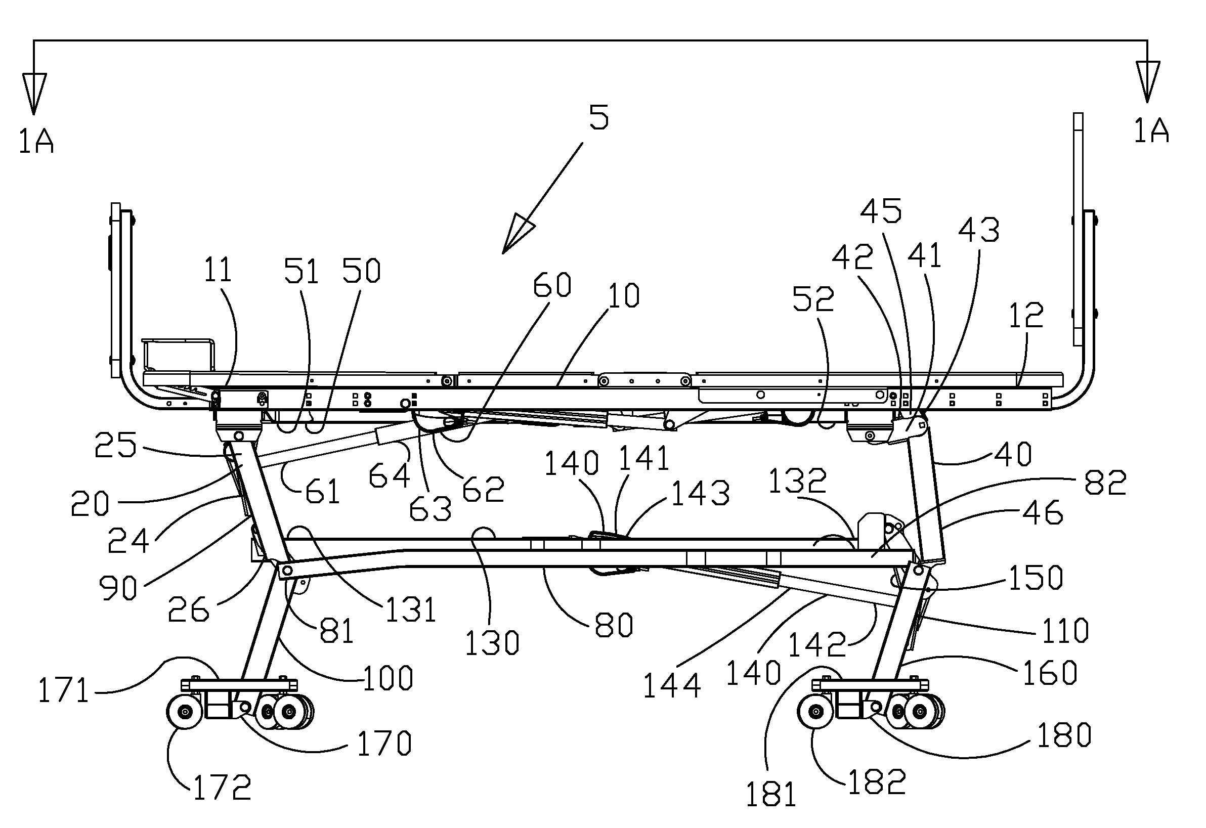
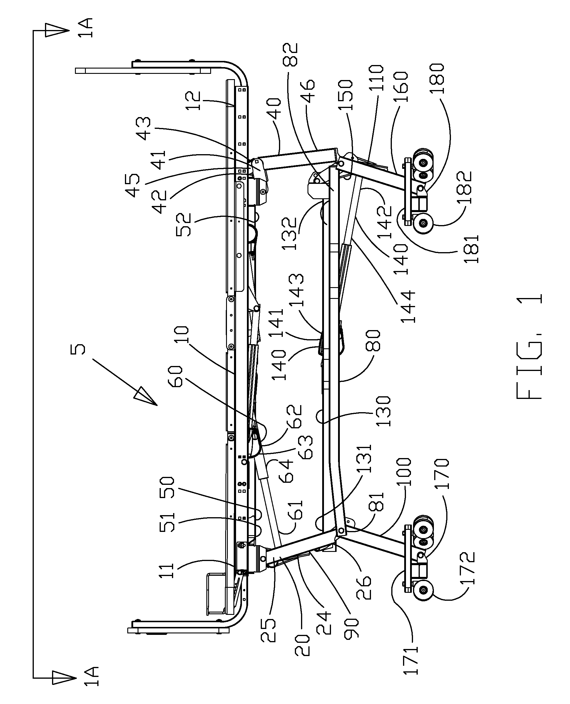
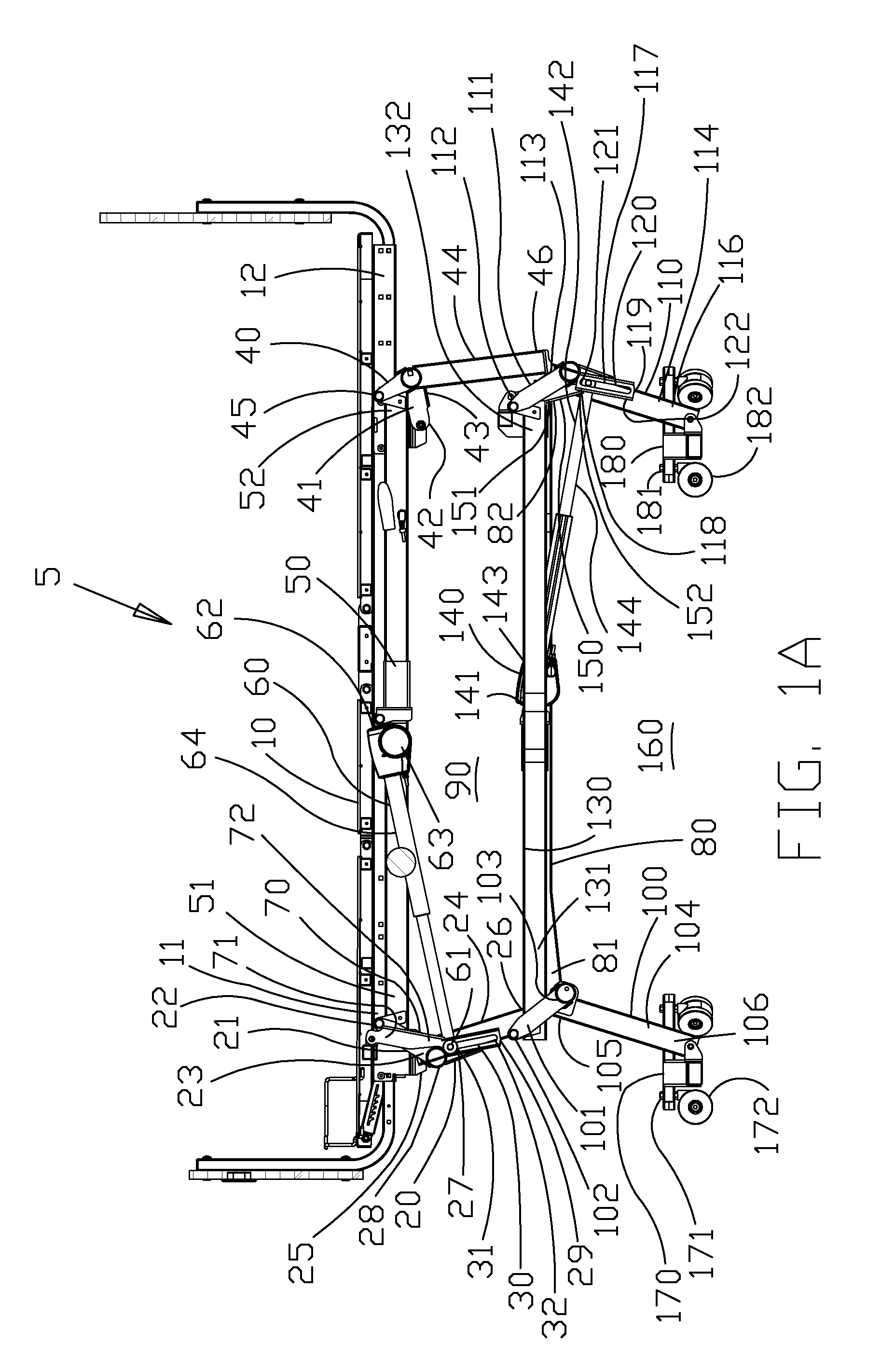
[0045]A bed 5 is provided according to one embodiment of the present invention as shown in FIGS. 1-10. The bed 5 has a main-frame and deck, hereafter referred to collectively as a deck 10. The deck 10 has a first end 11 and a second end 12.

[0046]A first lever 20 is preferably at the first end 11 of the deck 10. The first lever 20 has arms 21, 24 and 27. The arms 21, 24 and 27 are rigidly connected to a cross-beam. The arms 21, 24 and 27 rotate about a central axis at the same rate. The cross-beam need not be concentric with the central axis. Arm 21 has a first end 22 and a second end 23. Arm 24 has a first end 25 and ...


PUM


Abstract

The present invention has a deck supported by at least one parallelogram. When two parallelograms are used, the first has first and second levers and a drag link, and the second has third and fourth levers and a second drag link. Each parallelogram is raised and collapsed with an actuator. The first lever and the fourth lever each have an arm with an interface. The actuators are pivotally and movably connected to the interfaces and pivotally connected to the drag links. The location of the actuators relative the interfaces is controlled with control arms. The control arms have ends that are connected to the respective drag link and each rotates at an offset circular path about a central point of the adjacent levers.

Description

[0001]This application is a continuation-in-part of United States Utility Application having Ser. No. 12 / 005,467 filed on Dec. 26, 2007, now U.S. Pat. No. 7,849,538 which itself is a continuation-in-part of United States Utility Application having Ser. No. 11 / 173,491 filed on Jun. 30, 2005, now U.S. Pat. No. 7,421,748 the contents of each are hereby incorporated herein by reference.BACKGROUND OF THE INVENTION[0002]1. Field of the Invention[0003]The present invention relates to an apparatus, such as a bed, having a vertically adjustable deck that is selectably raised and lowered with at least one actuator operating with improved loading characteristics.[0004]2. Description of the Related Art[0005]Typically, height and angle adjustable beds are used by medical institutions, such as hospitals and nursing homes. The beds usually include a bed frame and an articulating mechanism for lowering the bed frame to a low position and raising the bed frame to a high position so that it may be us...

Claims


Application Information

Patent Timeline
Patent Type & Authority Patents(United States)
IPC IPC(8): A47B7/00
CPCA61G7/012
Inventor EDGERTON, JOHN
Owner GF HEALTH PRODS
Why Eureka
Try Eureka