
Load handling device

a technology of handling device and resistance load, which is applied in the direction of mechanical equipment, tyre parts, tire repairing, etc., can solve the problems of high cost and achieve the effect of reducing the manufacturing and maintenance costs of the machin

Active Publication Date: 2012-12-04
BUTLER ENG & MARKETING
View PDF11 Cites 2 Cited by
  • Summary
  • Abstract
  • Description
  • Claims
  • Application Information

AI Technical Summary

Benefits of technology

[0010]Another object of the present invention is to provide a tire assembling-disassembling machine provided with a handling device suitable for reducing the manufacturing and maintenance costs of the machine with respect to prior art machines.

Problems solved by technology

Moreover, when very high levels are to be reached, or loads are to be moved between two quite distant levels, a jack suitable for carrying out a stroke of considerable length must be used, which involves high costs.
However, if the jack does not work in a vertical trim, a bending moment approximately proportional to the length of the jack occurs at the free end of the stem.

Method used


Image

  • Load handling device
  • Load handling device

Examples


Embodiment Construction

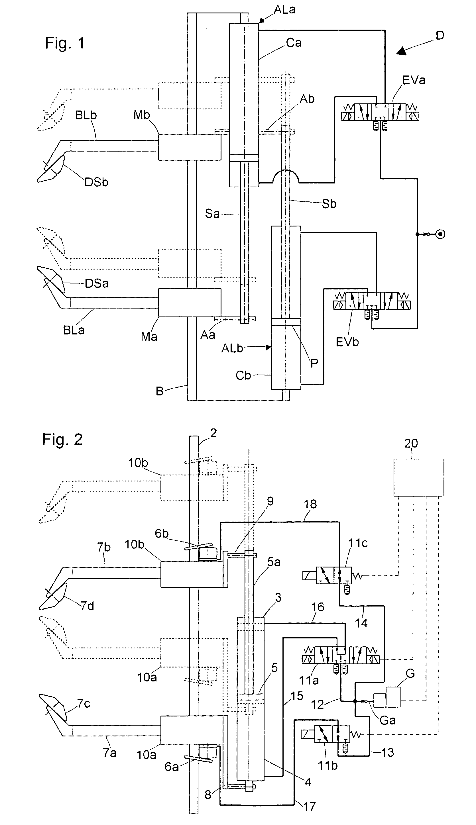
[0029]With reference first to FIG. 1, a device D for handling a pair of work arms BLa, BLb according to the prior art has been schematically shown, which comprises a support structure B, two linear double-acting piston-cylinder actuators, e. g. two pneumatic jacks ALa, ALb, each jack comprising a cylinder Ca, Cb and a respective piston rod Sa, Sb which protrudes therefrom and is controlled by a piston P slidingly mounted into the cylinder. The cylinder of each actuator is secured, e. g. welded, to the support structure B. The two actuators are arranged parallel but opposite to one another, i. e. the actuator ALa has its piston rod Sa extending in one direction and that of the actuator ALb in the opposite direction.

[0030]Each piston rod Sa, Sb is fixed at its free end, e. g. by means of a respective support rod Aa, Ab, to a sleeve Ma, Mb, respectively, slidingly mounted on a guide track PS extending parallel to the actuators ALa and ALb and supporting a respective cantileverwise-exte...


PUM

PropertyMeasurementUnit
lengthaaaaaaaaaa
resistant forceaaaaaaaaaa
heightaaaaaaaaaa

Abstract

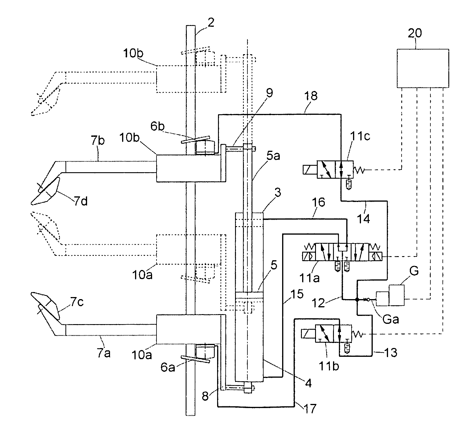
A handling device for a resistant load includes a guide track (2) or a plurality of parallel guide tracks, a pair of slides or carriages (10a, 10b) slidingly mounted on a guide track (2) or a respective guide track, removable locking means (6a, 6b) associated with each slide or carriage (10a, 10b) and designed to keep in position its respective slide or carriage along the respective guide track (2), a linear actuator means (3) associated with each slide or carriage (10a, 10b) and having at least one first component (4) and at least one second component (5a) which can be displaced, upon control, one with respect to the other parallely to the guide track (2) or plurality of parallel guide tracks, the at least one first component (4) being displaceable together with a slide or carriage (10a) of the pair, and the at least one second component (5a) being displaceable together with the other slide or carriage (10b) of the pair, engagement means (7a, 7b) for a resistant load displaceable together with the linear actuator means, and control means designed to control the removable locking means (6a, 6b) and the linear actuator means (3).

Description

FIELD OF INVENTION[0001]The present invention relates to a resistant-load handling device having in particular one or more work arms and being particularly suitable for handling two arms designed to support a tire bead releasing, assembling or disassembling tools for vehicle tires.BACKGROUND OF INVENTION[0002]Work arms, e.g. of tire assembling-disassembling machines or plate / plane support arms, such as raising machine arms (e. g. cranes) designed to displace loads between different levels, are suitably handled by means of an actuator comprising, for example, a fluid-operated group having its cylinder anchored to a base (e. g. a base of a crane) and a piston rod protruding from the cylinder, whose free end is designed to support a work arm.[0003]First of all, with such a solution a jack or another linear actuator for each working arm should be used. Moreover, when very high levels are to be reached, or loads are to be moved between two quite distant levels, a jack suitable for carryi...

Claims


Application Information

Patent Timeline
Patent Type & Authority Patents(United States)
IPC IPC(8): B23P19/04B60C25/132B21D53/26B65G1/137
CPCB60C25/138Y10T29/53852Y10T29/49494
Inventor GONZAGA, TULLIOSANTI, SILVANO
Owner BUTLER ENG & MARKETING
Learn More