Channel switching valve

a channel switching valve and valve body technology, applied in the direction of valve operating means/release devices, machines/engines, instruments, etc., can solve the problems of increased rotational torque of the channel switching valve, fluid leakage, cross-contamination, etc., to increase the lifetime of the valve, reduce the pressing force applied by the elastic member, and easy to change

Active Publication Date: 2012-12-04
SHIMADZU CORP
View PDF19 Cites 19 Cited by
  • Summary
  • Abstract
  • Description
  • Claims
  • Application Information

AI Technical Summary

Benefits of technology

[0012]It is therefore an object of the present invention to provide a channel switching valve having improved durability.
[0017]According to the present invention, the stroke of the elastic member urging the rotor toward the stator can be changed by the adjusting system. Therefore, a pressing force applied by the elastic member can be reduced when liquid is allowed to flow under low pressure, which makes it possible to increase the lifetime of the valve.
[0018]Further, the stroke of the elastic member can be more easily changed by providing, as the adjusting system, a protruding / recessed pattern on connecting surfaces of both the stator and the rotor or on connecting surfaces of both the rotor and the shaft. In this case, the stroke of the elastic member is changed depending on whether the protruding / recessed patterns of the connecting surfaces are fitted into each other or not.

Problems solved by technology

Therefore, the contact surface of the rotor is worn out due to the prolonged use of the channel switching valve.
This may cause an increase in the rotational torque of the channel switching valve, fluid leakage, and cross-contamination by liquid remaining in the worn-out contact surface of the rotor.
Therefore, in a case where the rotor is made of resin, the contact surface of the rotor is scraped off and scrapings are generated by friction caused by the rotation of the rotor.
In this case, the scrapings from the rotor also flow into a column connected downstream from the channel switching valve, which becomes the cause of deterioration of the column.
However, if such contact surfaces are pressed against each other by a great force, a so-called “linking” phenomenon in which mirror-polished surfaces adhere to each other occurs, which interferes with the rotation of the rotor.
In this case, however, there is a problem that the rotor always pressed against the stator by a great force is significantly worn out by its rotation, which leads to a shorter life expectancy of the valve.
Despite this, in the case of conventional channel switching valves, the pressing force of a rotor against a stator is constant and cannot be changed.

Method used


Image

  • Channel switching valve
  • Channel switching valve
  • Channel switching valve

Examples


first embodiment

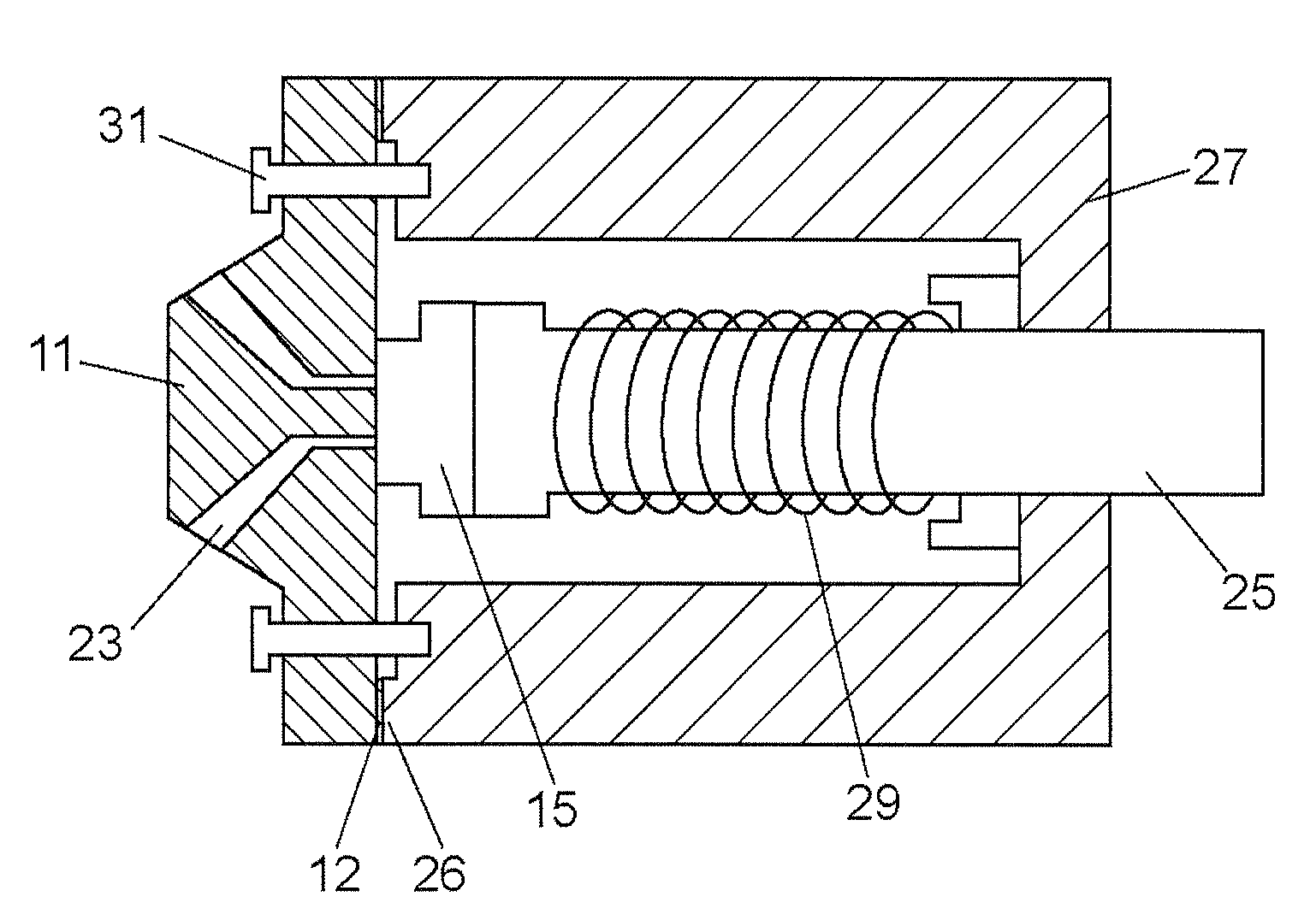
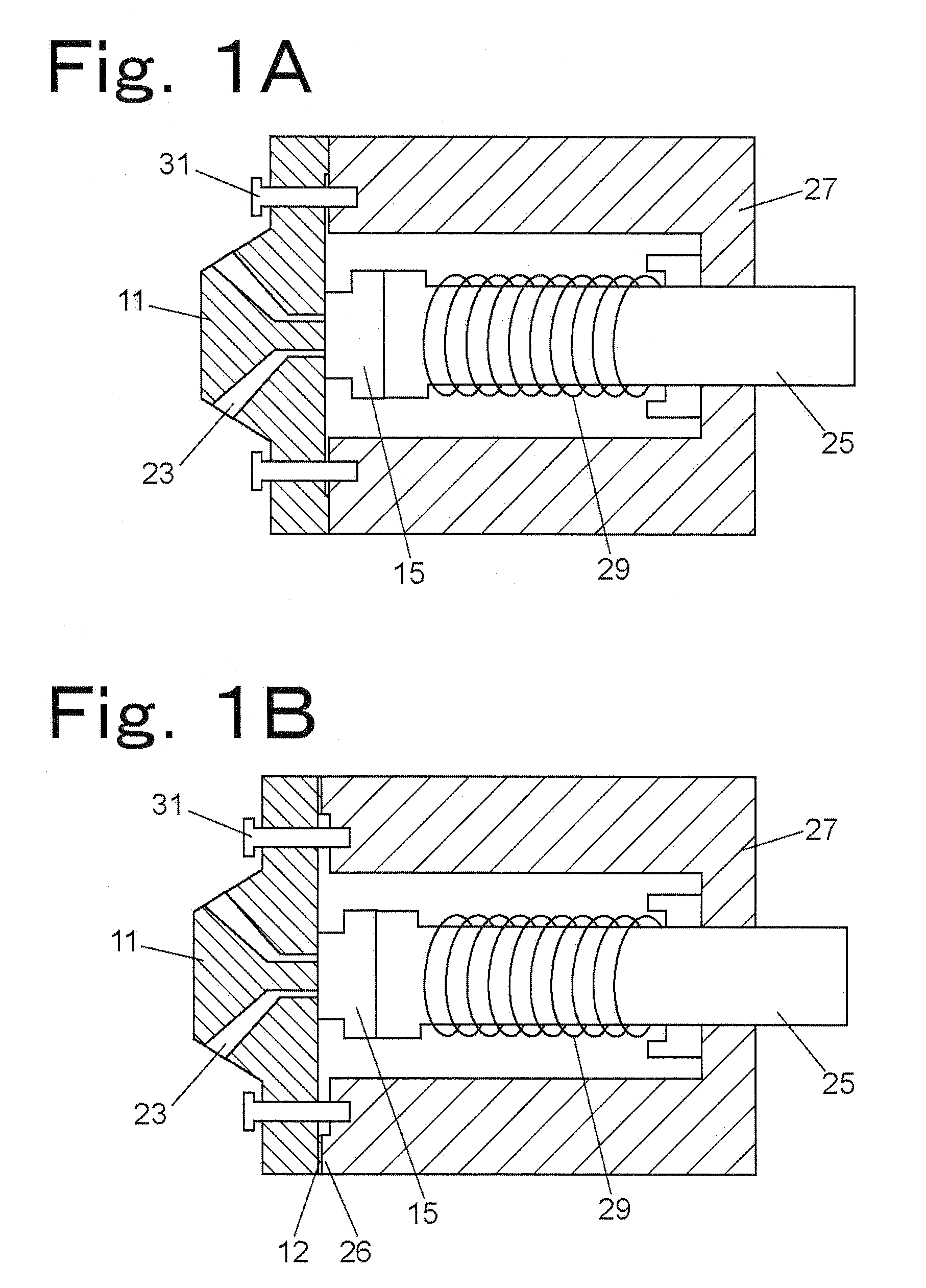
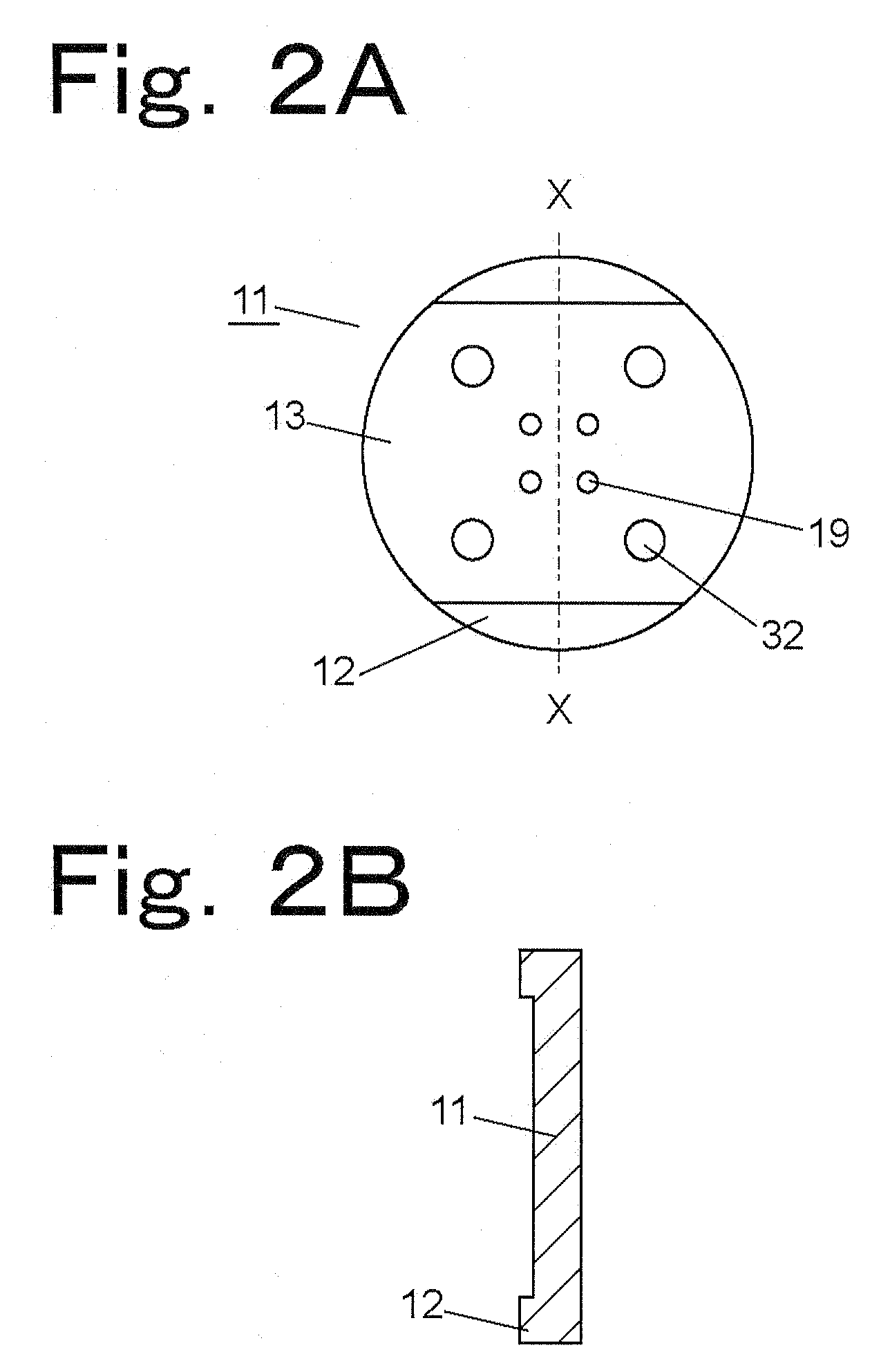
[0042]FIGS. 1A and 1B are schematic views showing the structure of a channel switching valve according to a first embodiment of the present invention. FIG. 1A and FIG. 1B show two states of the channel switching valve, between which the stroke of a coil spring as an elastic member is changed by rotating one of a stator 11 and a body section 27. More specifically, FIG. 1A shows a state where the stroke is shortened and FIG. 1B shows a state where the stroke is lengthened. FIGS. 2A and 2B show the stator 11 of the channel switching valve according to the first embodiment of the present invention, FIGS. 3A and 3B show the body section 27 of the channel switching valve according to the first embodiment of the present invention, and FIG. 3C shows a rotor 15 placed in the body section 27.

[0043]The stator 11 is made of stainless steel, and is integrally formed with a housing top to which flow channels are to be connected. The stator 11 has a contact surface 13 being in contact with the rot...

second embodiment

[0054]FIGS. 4A and 4B are perspective views of the rotor 15 placed in the body section 27 and the shaft 25 of a channel switching valve according to a second embodiment of the present invention. The upper surface of the rotor 15 shown in FIG. 4 is a contact surface being in contact with the stator 11. The rotor 15 has the grooves 21 each of which interconnects the channel connecting portions of the stator 11. In the second embodiment, the stator 11 and the body section 27 remain fixed to each other, but the rotor 15 and the shaft 25 each have a connecting surface and are removably fixed to each other at their connecting surfaces.

[0055]The shaft 25 is rotatably supported by the body section 27, and a flange 22 is provided at the distal end of the shaft 25. The positioning of the rotor 15, that is, the fixation of the rotor 15 to the shaft 25 is achieved by attaching the rotor 15 to the flange 22 with bolts. The connecting surface of the flange 22 and the connecting surface of the rot...


PUM


Abstract

A channel switching valve is disclosed. The channel switching valve has a stator and a body section each having a connecting surface. The stator and the body section are removably fixed to each other by bolts at their connecting surfaces. Each of the connecting surfaces has a protruding / recessed pattern formed thereon, and the patterns are designed to fit into each other. By rotating the stator and the body section relative to each other, the stroke of a spring is changed between a position where the protruding / recessed patterns of the stator and the body section are fitted into each other and a position where they are not fitted into each other. The spring is held in the body section in its compressed state to urge the rotor toward the stator. An urging force for pressing the rotor against the stator is adjusted by changing the stroke of the spring.

Description

BACKGROUND OF THE INVENTION[0001]1. Field of the Invention[0002]The present invention relates to a channel switching valve for use in liquid chromatographs and the like.[0003]2. Description of the Related Art[0004]High-performance liquid chromatographs have a flow channel, through which liquid flows under high pressure, and require channel switching.[0005]For such a purpose, a channel switching valve is conventionally used. A conventional channel switching valve includes a stator to be connected to flow channels and a rotor, and is configured to perform channel switching by rotating the rotor in a state where the stator and the rotor are in contact with each other at their surfaces (see Japanese Unexamined Patent Publication No. 1-307575).[0006]In such a channel switching valve, the contact surface of the stator has ports to be connected to flow channels and the contact surface of the rotor has a switching groove for interconnecting two of the ports of the contact surface of the sta...

Claims


Application Information

Patent Timeline
Patent Type & Authority Patents(United States)
IPC IPC(8): F16K11/074F16K11/06
CPCF16K1/02F16K1/34F16K31/002G01N30/20G01N35/1097G01N2030/201G01N2030/202F16K3/10F16K11/0743Y10T137/86501Y10T137/86863
Inventor TOMITA, MASAMI
Owner SHIMADZU CORP
Why Eureka
Try Eureka