
Wheel axle lifter

a technology which is applied in the direction of suspensions, vehicle springs, resilient suspensions, etc., can solve the problems of only having two pairs of wheels, affecting the lifting effect, and causing the rubber mat and the suspending arm to be easily damaged, so as to achieve the effect of lifting and lowering the wheel axl

Inactive Publication Date: 2012-12-04
CHUAN TA KING ENTERPRISE CO LTD
View PDF12 Cites 6 Cited by
  • Summary
  • Abstract
  • Description
  • Claims
  • Application Information

AI Technical Summary

Benefits of technology

[0007]The main object of the present invention is to provide a wheel axle lifter with better effect of lifting and lowering the wheel axle, and the wheel axle lifter is used for being adapted to be disposed with auto-mobiles.
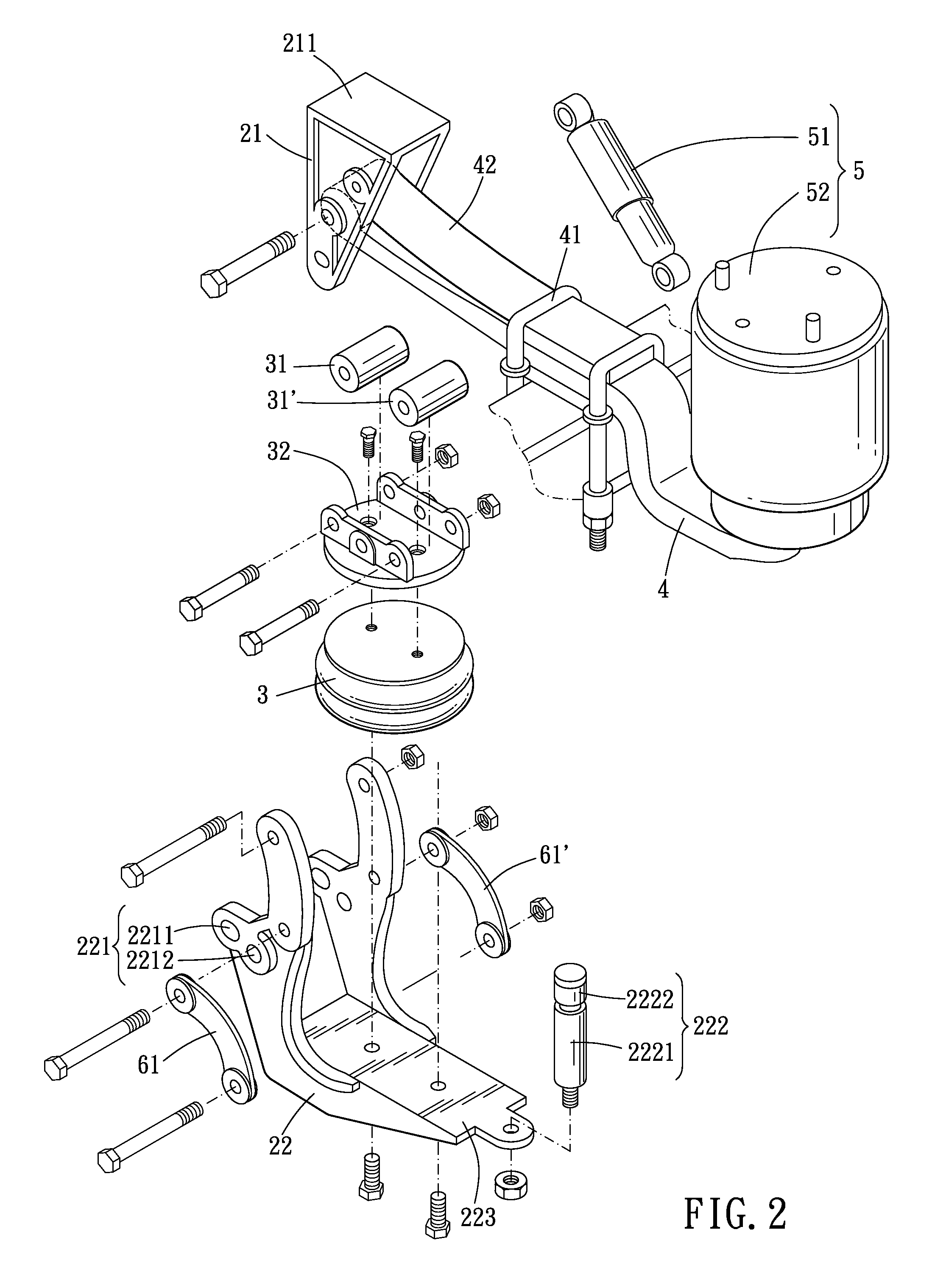
[0011]As such, because the first airbag includes at least two rollers, each one of the two rollers abuts against the protecting member by more contacting area. And the loading pressure of the first airbag becomes smaller when driving the suspending arm to move. Also, the first airbag can lift the wheel axle up easier and more stable in a process of operation. Rotating ability for the two rollers decreases a friction in a process of pushing the suspending arm to move. As a result, the two rollers and the suspending arm would not be damaged easily.

Problems solved by technology

However, the auto-mobile needs only two pairs of the wheels for driving on the roads when the auto-mobile loads no cargo.
In the long term, the use of the steel spring still causes a great possibility of being damaged to the airbag.
And the great friction between the rubber mat and the suspending arm also lead the rubber mat and the suspending arm to be damaged easily.
Apart from being deformed, the lifting device tends to be damaged easily on account of pushing for a long time.
And a cost on repairing is increased.

Method used


Image

  • Wheel axle lifter
  • Wheel axle lifter
  • Wheel axle lifter

Examples


Embodiment Construction

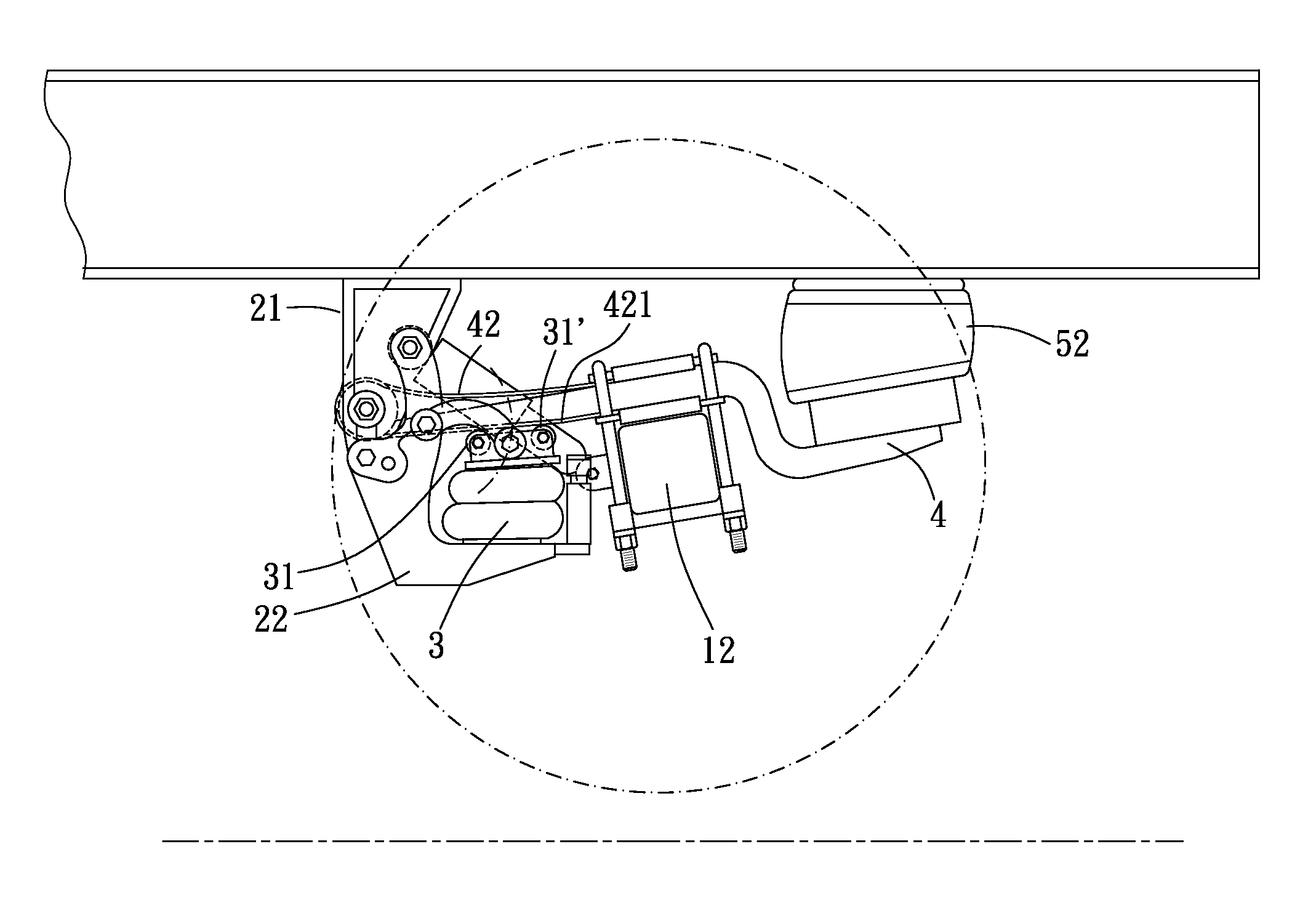
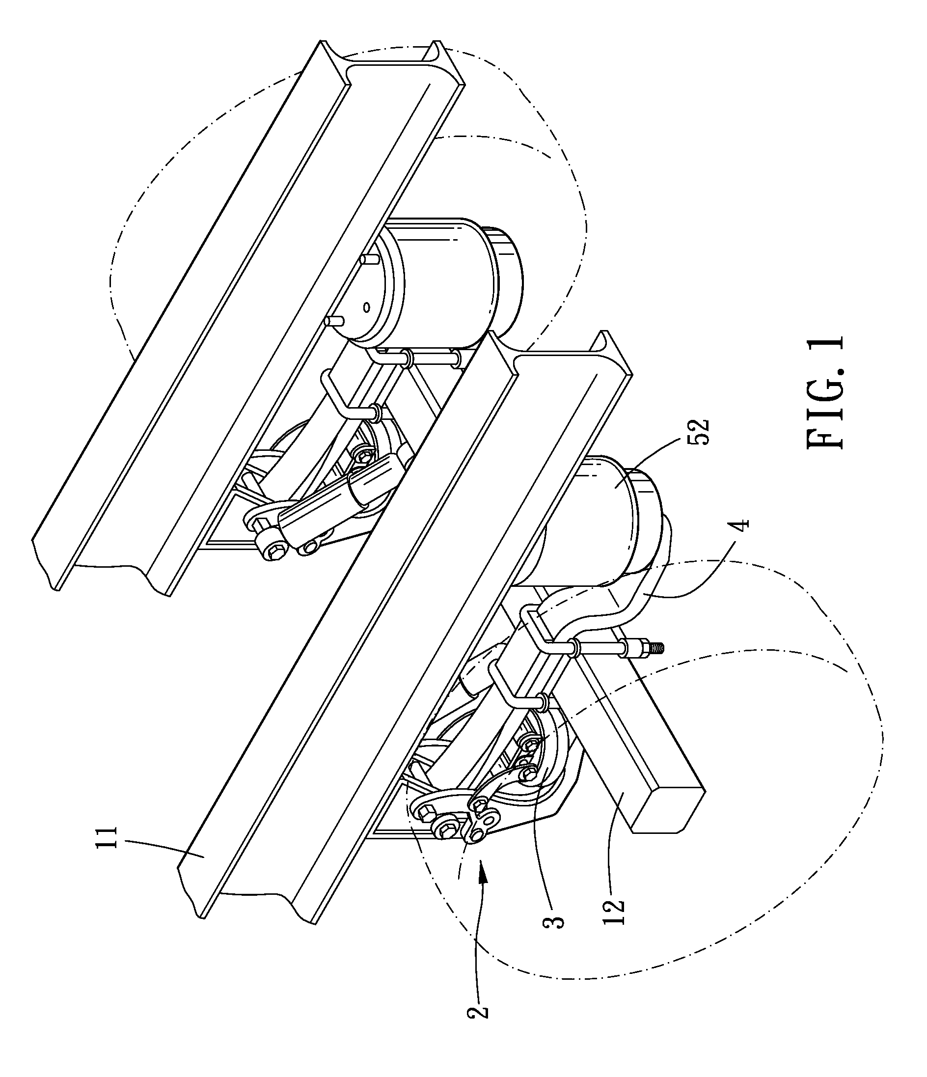
[0018]Please refer to FIG. 1 and FIG. 2, the wheel axle lifter of the present invention can be used for being adapted to be disposed with auto-mobiles such as trucks and trailers. The auto-mobile comprises a body 11 of the auto mobiles and a wheel axle 12, and the wheel axle lifter comprises a fixing portion 2, a first airbag 3, a suspending arm 4 and a damp mechanism 5.

[0019]The fixing portion 2 is disposed with the body 11 of the auto mobile, and the first airbag 3 is disposed with the fixing portion 2. The first airbag 3 has at least two rollers 31, 31′, and the two rollers 31, 31′ are spaced apart. One end of the suspending arm 4 is pivotally disposed with the fixing portion 2. A middle portion of the suspending arm 4 is disposed with the wheel axle 12. The suspending arm 4 is movable between a first position and a second position. Note that each one of the two rollers 31, 31′ are capable of rotating, and the two rollers 31, 31′ contact the suspending arm 4 when the first airbag...


PUM


Abstract

The present invention provides a wheel axle lifter used for being adapted to be disposed with auto-mobiles. The wheel axle lifter comprises a fixing portion, a first airbag and a suspending arm. The fixing portion is used for being disposed with a body of the auto-mobile. The first airbag disposed with the fixing portion comprises at least two rollers. The two rollers are positioned integrally. One end of the suspending arm is pivotally disposed with the fixing portion. The suspending arm is disposed with a wheel axle and is able to move between a first position and a second position. Each one of the two rollers rotationally contacts with the suspending arm when the first airbag drives the two rollers upward to abut against the suspending arm so that the suspending arm moves to the second position.

Description

BACKGROUND OF THE INVENTION[0001]1. Field of the Invention[0002]The present invention relates to the field of a wheel axle lifter used for being adapted to be disposed with auto-mobiles.[0003]2. Description of the Prior Art[0004]Speaking of auto mobiles such as trucks and trailers, a body of an auto-mobile is disposed with pairs of wheels to even the loading weight for a reason that the auto-mobile has to transport cargos with huge sizes and heavy weight on roads. However, the auto-mobile needs only two pairs of the wheels for driving on the roads when the auto-mobile loads no cargo. Under this condition of loading no cargo, the auto-mobile such as trucks and trailers would be disposed with a wheel axle lifter to lift up other pairs of the wheels so that the pairs of the wheels lifted would not contact with the ground, decreasing friction between the wheels and the ground and consumption of power needed for overcoming the friction. Thus, a radius on making a U-turn can also be small...

Claims


Application Information

Patent Timeline
Patent Type & Authority Patents(United States)
IPC IPC(8): B62D61/12B60G11/26
CPCB60G9/003B60G11/27B62D61/12B60G2204/4702B60G2202/152
Inventor YAO, YU-HSIA
Owner CHUAN TA KING ENTERPRISE CO LTD
Learn More