Vision testing apparatus and method

a technology for testing apparatus and vision, applied in the field of vision testing, can solve the problems of difficult to travel to the nearest airport, and high cost of equipment required to perform these tests,

Active Publication Date: 2012-12-04
CITY UNIV
View PDF11 Cites 38 Cited by
  • Summary
  • Abstract
  • Description
  • Claims
  • Application Information

AI Technical Summary

Problems solved by technology

Whilst these systems have been shown to be effective in vision testing and have enabled subjects' visual performance to be accurately assessed, it is generally the case that the equipment (in particular the display) required to perform these tests is typically very expensive and hence tends only to be accessible at selected hospitals or research centres.
As the equipment tends not to be universally provided, users can often live a relatively long way from the nearest hospital that has the facility to undertake these tests.
Travelling to these hospitals is not too much of a problem for able-bodied users, but can be problematic for less able users who cannot travel so easily.
The use of such tests for mass screening of diseases of the eye is therefore very limited.
It is also the case that in less developed regions of the world the cost of the equipment is such that the majority of hospitals simply do not have the funds available to acquire the equipment they would need to implement these tests.
One unfortunate consequence of this is that many users continue to endure conditions that could perhaps be treated if their vision were to be properly investigated.
However, whilst an easier and less expensive implementation of such tests would undoubtedly be an improvement to existing arrangements, there will still be those users for whom travel is impossible and those hospitals that are still unable to afford the equipment.
However, the problem here is that the tests are carefully designed to have particular visual characteristics, and it would be very difficult to ensure that reproduced tests still have those characteristics when the visual equipment used for the purpose is likely to differ widely from user to user.

Method used


Image

  • Vision testing apparatus and method
  • Vision testing apparatus and method
  • Vision testing apparatus and method

Examples


Embodiment Construction

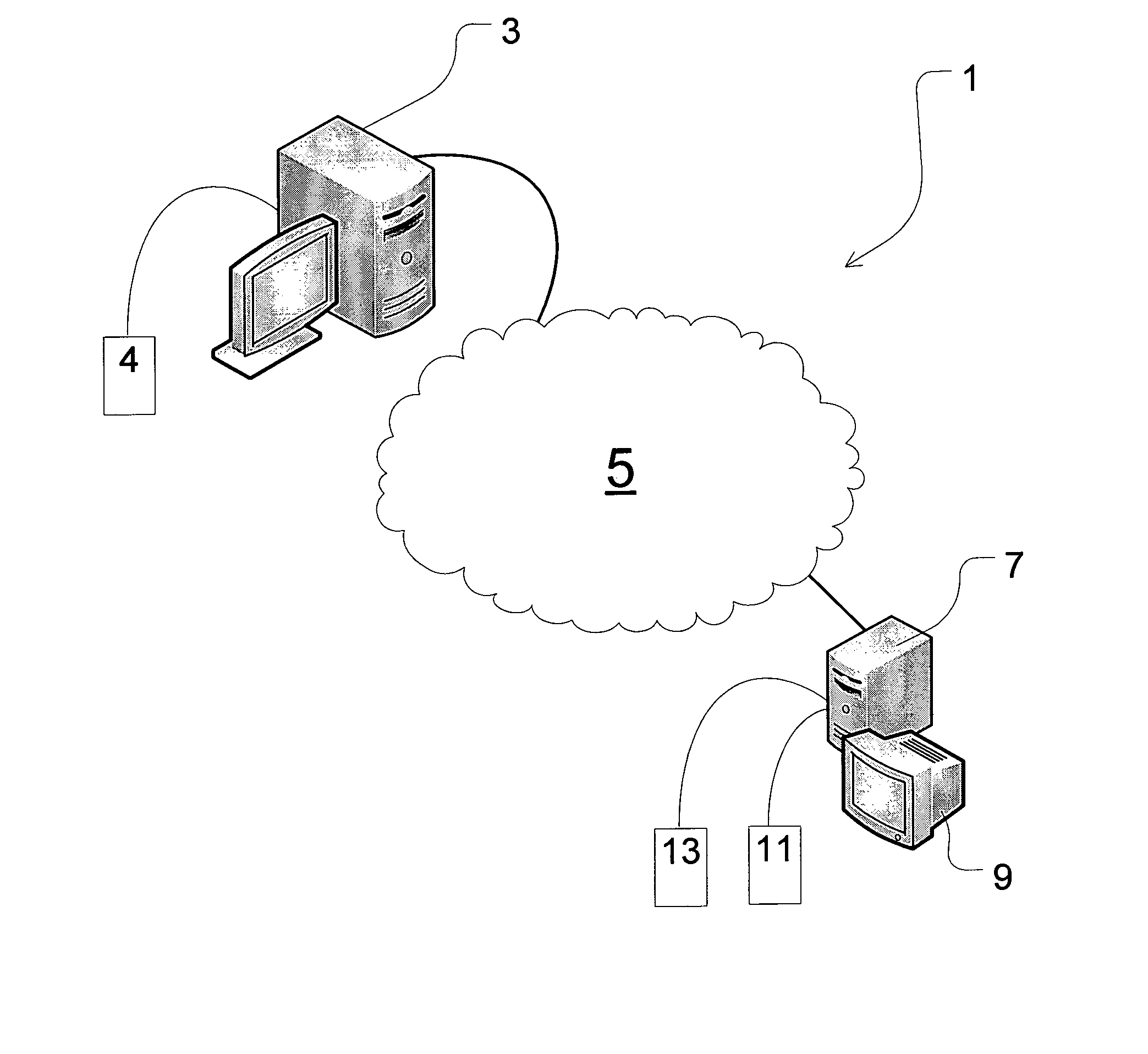
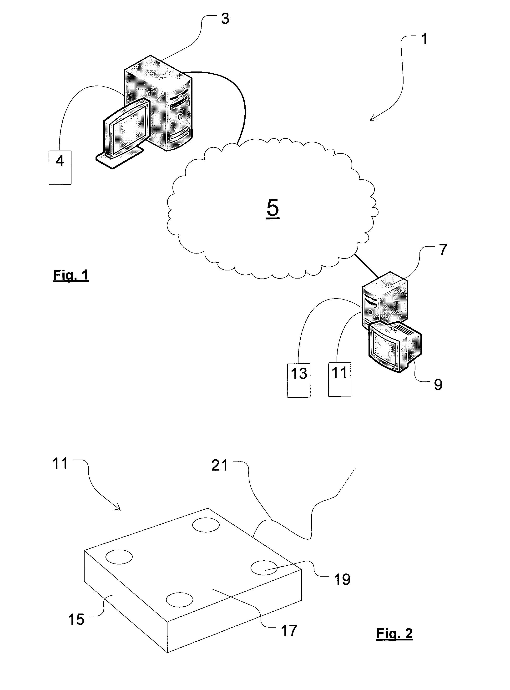
[0042]Referring now to FIG. 1, there is shown an illustrative embodiment of the optometric system 1 according to a preferred embodiment of the present invention.

[0043]The system comprises a computing resource, such as a personal computer, that is configured as a test server 3 operable to generate vision tests for display to a user. The server is coupled to a data store 4 (comprising, for example, one or more hard disk drives) in which one or more reference visual tests are stored, each of those reference visual tests comprising a plurality of images that make up a given visual test, the images and the test as a whole being optimised for display on a high quality display with performance characteristics as close as possible to those of an ideal display.

[0044]The test server 3 is coupled by way of a communications network 5 to a second computing resource, such as a personal computer, that is configured as a user terminal 7. The user terminal is coupled to a display device 9 (typically...


PUM


Abstract

An embodiment of the invention relates to vision testing apparatus comprising: a local display (9); means (13) for obtaining data characterising the performance characteristics of said local display; means (9) for displaying to a user at said local display, a vision test that comprises an adaptation of a reference vision test; means (11) for registering user input in response to said displayed vision test; and means (9) for providing the user with the results of said displayed test; wherein said reference vision test comprises a test that is optimised for display on a high quality display, and the vision test for display at said local display is obtained by adapting said reference test in accordance with said characterising data so that the vision test displayed on said local display is a faithful reproduction of said reference test.

Description

FIELD OF THE INVENTION[0001]This invention relates to vision testing, for example testing to assess visual performance. Particularly preferred embodiments of the invention relate to a method for measuring visual sensitivity and to apparatus for implementing that method. By way of example, such testing can prove to be useful in assessing minimum vision requirements in specified occupational environments and for detecting changes in visual sensitivity caused by disease or for monitoring the outcome of treatment.BACKGROUND TO THE INVENTION[0002]A variety of occupational, visual tests have previously been proposed for the assessment of various aspects of visual performance. For example, colour vision screening has previously been used as a means for detecting colour deficiencies, and as a means for assessing the severity of a user's colour vision loss.[0003]Colour vision testing has also been used to determine whether a user's vision meets the colour vision requirements for a given occu...

Claims


Application Information

Patent Timeline
Patent Type & Authority Patents(United States)
IPC IPC(8): A61B3/02
CPCA61B3/18A61B3/0041
Inventor BARBUR, JOHN LAZARHARLOW, JONATHAN ALISTER
Owner CITY UNIV
Why Eureka
Try Eureka