Method for manufacturing a bendable tube

a manufacturing method and bendable technology, applied in the direction of manufacturing tools, mechanical equipment, applications, etc., can solve the problems increasing the effort, and so as to simplify the removal of the tube section. , the effect of reducing the effective width of the previously manufactured separating gap

Inactive Publication Date: 2012-12-11
RICHARD WOLF GMBH
View PDF33 Cites 9 Cited by
  • Summary
  • Abstract
  • Description
  • Claims
  • Application Information

AI Technical Summary

Benefits of technology

[0004]Against this background, it is an object of the invention to provide a method for manufacturing a bendable tube with improved stability characteristics, the method being simpler and thus more economical with regard to manufacturing technology.
[0007]According to an embodiment of the invention, after the separation of the tube into several tube sections one envisages arranging means for producing a positive fit transverse to the axis direction of the tube, peripherally, i.e., on the outer side of the peripheral surface of the tube sections, at regions of the tube sections, which are situated in engagement with one another, wherein these means advantageously stabilize the joint connections of the individual tube sections. Here, one must typically take care to design and / or arrange these means such that a bending of the tube sections which are situated in engagement with one another, to one another, is not prevented.
[0011]Apart from this, it may also be advantageous to widen the separating gap between the tube sections of the enveloping tube, such that the regions of the bendable tube, which axially border the lugs and recesses of the individual tube sections, lay completely bare. Accordingly, whole, annular sections of the enveloping tube, which in the installed position of the bendable tube in the enveloping tube do not cover the regions of the bendable tube which are situated in engagement, may be cut out, so that only narrow, annular sections of the enveloping tube, which in each case stabilize the tube sections of the bendable tube, which are situated in engagement with one another, without limiting the bending ability, are left standing radially on the outer side of the regions of the tube sections of the bendable tube, the regions being in engagement with one another.
[0013]Previously however, one preferably envisages welding the enveloping tube at least one web end to the bendable tube arranged therein, or connecting it in any other suitable manner. For this, the end of this web should typically be arranged on the outer side of a wall region of the bendable tube. Preferably, the enveloping tube at the ends of all webs formed on the enveloping tube is welded to the bendable tube, in order to fasten all tube sections covering the regions of the tube sections of the bendable tube, which are engaged with one another, in the position on the bendable tube which is necessary for this. For welding the web ends of the enveloping tube to the bendable tube, one may apply any welding methods which are suitable of this. Preferably, one may apply those welding connections, such as laser welding, which permit a concentrated introduction of energy into the welding location and thus only lead to a negligible shape distortion of the tube sections.
[0015]As has already been noted, it may be necessary to cut out whole, annular sections of the enveloping tube, which in the installed condition of the bendable tube in the enveloping tube do not cover the regions of the bendable tube, which are in engagement. In order to simplify the removal of these tube sections, a separating gap running essentially in the axis direction of the enveloping tube is advantageously formed on them. This separating gap permits the tube sections provided with it to break open as the case may be, or to widen so far, that they may be removed from the bendable tube transversely to the longitudinal axis of this.
[0016]In a further advantageous embodiment of the method according to the invention for manufacturing a bendable tube, one envisages in each case designing at least one separating gap between the tube sections of the bendable tube, in a manner such that these tube sections first remain connected to one another via at least one web in the regions forming the positive fit between these tube sections, and are broken open by a bending of the bendable shaft which is subsequent to this. This is advantageous inasmuch as the material connection of the individual tube sections on inserting the bendable tube into the enveloping tube still exists, and the bendable tube accordingly may be handled as an individual component in a simple manner. An advantageous auxiliary effect after the breaking of the webs is to be seen in the fact that the effective width of the previously manufactured separating gap is reduced by the web ends which then arise and which continue to remain in the separating gap between the two separate tube sections, which leads to a correspondingly smaller play in the articulated connection of the tube sections.

Problems solved by technology

This procedural method is comparatively time-consuming and costly, wherein the effort is yet further increased with an increasing number of the required tube sections, as well as with a reducing size of these tube sections.
Moreover, bendable tubes manufactured in this manner only have a low stability transverse to the axial direction of the tube, since the tube sections may also inadvertently separate from one another just as they are joined together.
The disadvantage with this method, however, is that one may only manufacture those tubes which, with a stable positive-fit connection of adjacent tube sections, are bendable only in a very limited manner or, with a good bending ability only have limited stability in the regions, in which adjacent tube sections are engaged with one another.

Method used


Image

  • Method for manufacturing a bendable tube
  • Method for manufacturing a bendable tube
  • Method for manufacturing a bendable tube

Examples


Embodiment Construction

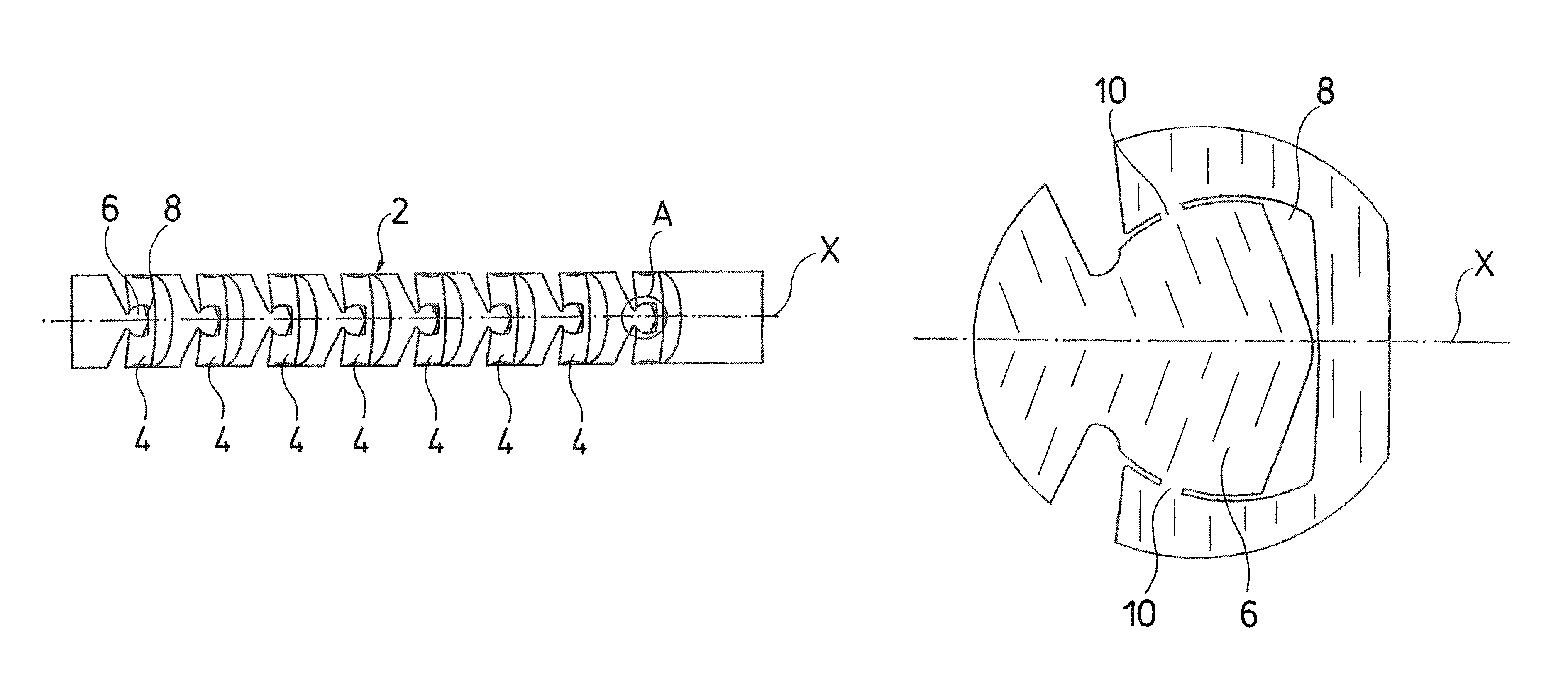
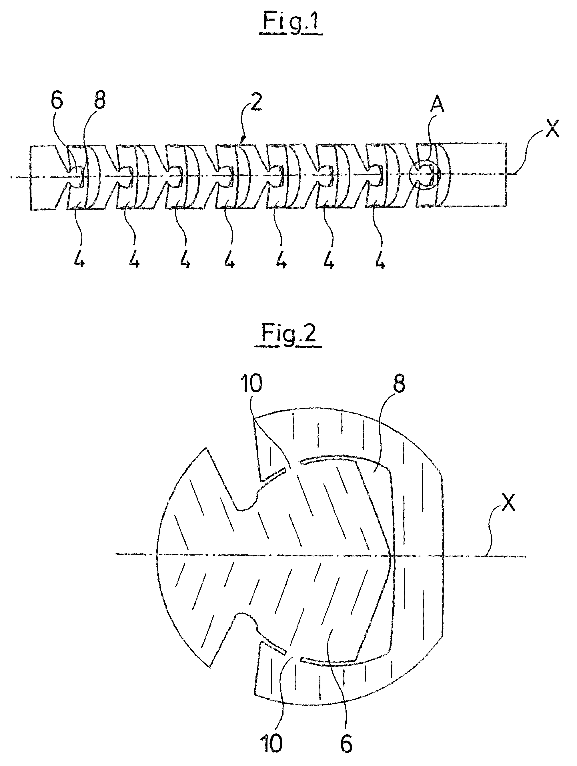
[0033]For manufacturing a bendable tube, two cylindrical tubes are used with the method according to the invention. With the manufacture of a bendable tube described by way of FIGS. 1 to 9, a tube 2 is divided peripherally into several tube sections 4 with a suitable separating method, preferably laser cutting. The separating gap between adjacent tube sections 4 is designed in a manner such that a lug 6, which is aligned in a direction of the longitudinal axis of the tube 2 and which engages into a recess 8 of the adjacent tube section 4, arises on a tube section 4 at two diametrically opposite sides.

[0034]The separation of the individual tube sections 4 from one another is carried out such that the lugs 6 first widen in a circular manner in the direction of the adjacent tube section 4, into which they engage, and then taper to a blunt tip on both sides in a beveled manner. The contour of the recesses 8 which are formed on the tube sections 4 is designed such that it runs essentiall...


PUM

PropertyMeasurementUnit
sizeaaaaaaaaaa
stabilityaaaaaaaaaa
thicknessaaaaaaaaaa

Abstract

With a method for manufacturing a bendable tube, which is preferably envisaged for an endoscopic instrument, first a tube is separated into several tube sections in a manner such that adjacent tube sections engage into one another with a positive fit in the axis direction of the tube. After the separation of the tube into several tube sections, one envisages peripherally arranging means for providing a positive fit transversely to the axis direction of the tube, on the regions of the tube sections, which are situated in engagement with one another.

Description

BACKGROUND OF THE INVENTION[0001]The invention relates to a method for manufacturing a bendable tube, in particular for an endoscopic instrument, in which a tube is separated into several tube sections in a manner such that adjacent tube sections engage into one another with a positive fit in the axis direction of the tube.[0002]It is known to manufacture tubes of this type, in which several tube sections may be bent or are connected to one another in an articulated manner, by lugs formed on the tube sections engaging into recesses of adjacent tube sections, such that first individual tube sections are manufactured which are then manually joined together for forming a tube. This procedural method is comparatively time-consuming and costly, wherein the effort is yet further increased with an increasing number of the required tube sections, as well as with a reducing size of these tube sections. Moreover, bendable tubes manufactured in this manner only have a low stability transverse ...

Claims


Application Information

Patent Timeline
Patent Type & Authority Patents(United States)
IPC IPC(8): B23P17/00B23P19/04A61B1/00
CPCA61B1/0055B21C37/15F16L11/18Y10T29/4981Y10T29/4998Y10T29/49877A61B1/008F16L9/22
Inventor KORNER, EBERHARD
Owner RICHARD WOLF GMBH
Why Eureka
Try Eureka