
In-line fused connector

a fused connector and connector technology, applied in the direction of electrical devices, coupling device connections, transportation and packaging, etc., can solve the problems of severe damage to the connector and the inability to easily access the fuses inside the modul

Active Publication Date: 2012-12-11
TYCO ELECTRONICS LOGISTICS AG (CH)
View PDF33 Cites 22 Cited by
  • Summary
  • Abstract
  • Description
  • Claims
  • Application Information

AI Technical Summary

Benefits of technology

The patent text describes three different in-line fused connectors that are designed to safely and efficiently connect power distribution modules to external electronic devices. These connectors have a fuse subassembly with a mating terminal and an internal terminal that can be easily engaged with the power distribution module and the electronic device, respectively. The fuse is removable and can be easily replaced if needed. The connectors are designed to provide a reliable and safe connection, even in high-current applications.

Problems solved by technology

For example, if a connector is unmated under active high voltage power, at the instant the mating conductors of the high voltage connector disconnect, the high voltage power may cause severe damage to the connector.
Due to the lack of alternative placement options, some known high voltage systems provide fuses inside power distribution modules.
For example, the fuses may not be easily accessible inside the module.

Method used


Image

  • In-line fused connector
  • In-line fused connector
  • In-line fused connector

Examples


Embodiment Construction

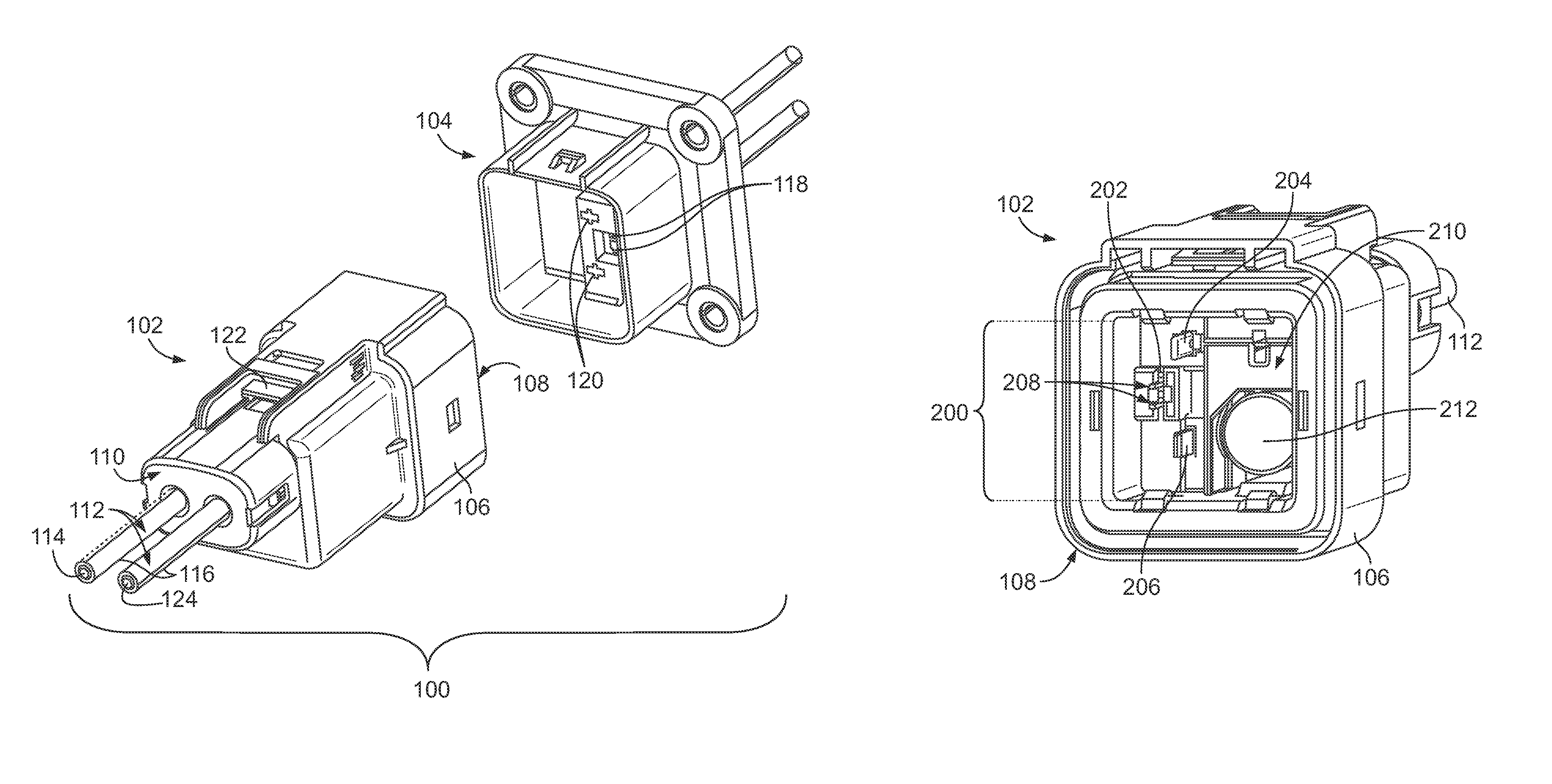
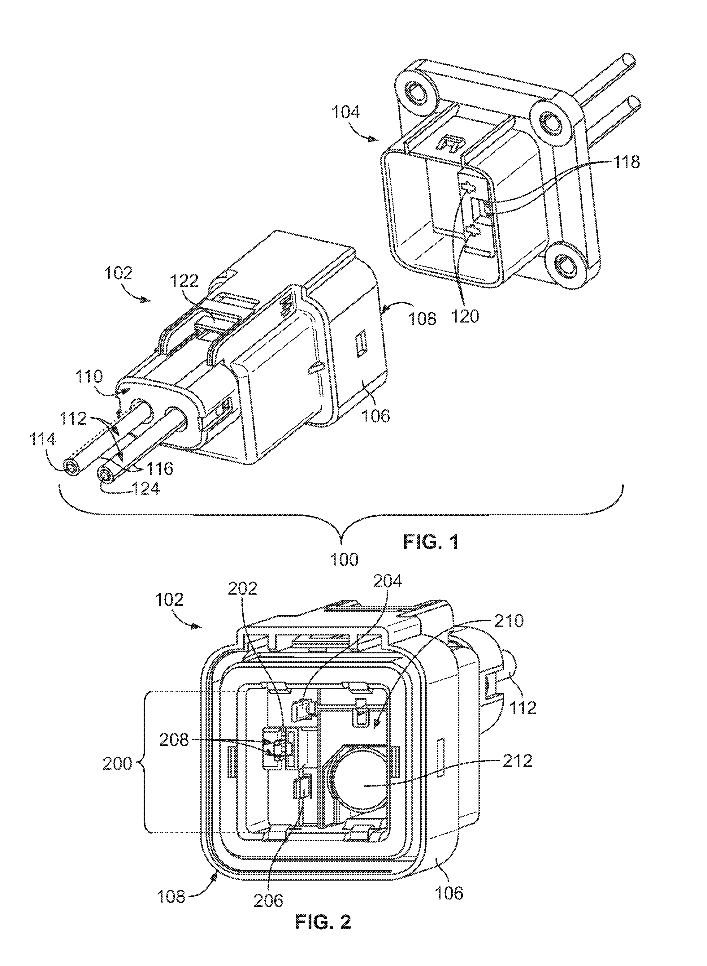
[0017]FIG. 1 is a perspective view of one embodiment of an unmated connector assembly 100. The connector assembly 100 is a high voltage connector assembly in one embodiment. For example, the connector assembly 100 may be capable of transferring electric power or current at voltages of at least 42 volts, at least 600 volts, or at lesser voltages. The connector assembly 100 may be used in conjunction with a vehicle, such as an automobile, to transfer electric current between two or more electronic devices or modules in an automobile.

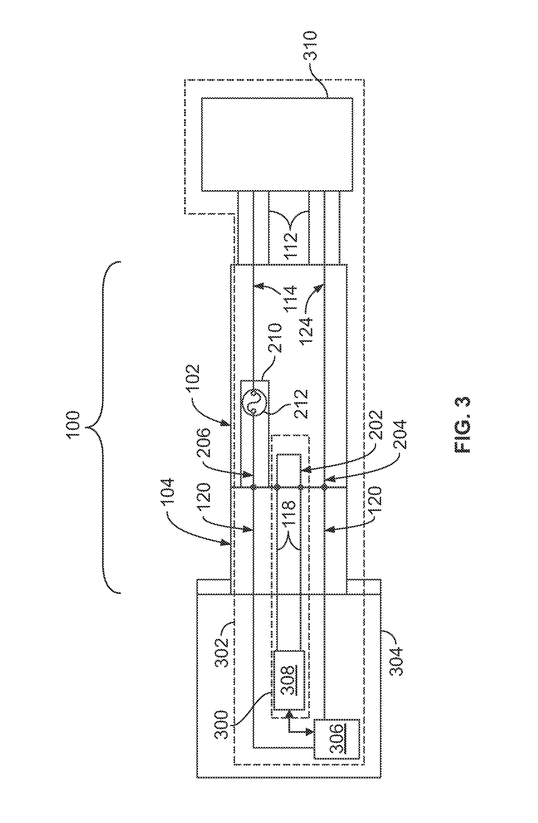
[0018]The connector assembly 100 includes an in-line fused connector 102 and a header subassembly 104. The in-line fused connector 102 and the header subassembly 104 mate to transfer relatively high voltage electric power therebetween. The header subassembly 104 can be part of a power distribution module, such as by being mounted to the exterior surface of a device in an automobile that includes or acts as a power source to supply electric current one or m...


PUM


Abstract

An in-line fused connector includes an outer housing and a fuse subassembly disposed in the outer housing. The fuse subassembly includes a mating terminal that is configured to engage a first conductive body of the power distribution module and an internal terminal coupled with the fused conductor that electrically couples with an electronic device. The mating terminal and the internal terminal are shaped to receive a fuse to electrically couple the mating terminal and the internal terminal. Electric current that is supplied by the power distribution module is conveyed through the fuse subassembly when the fuse subassembly receives the fuse and the mating terminal of the fuse subassembly mates with the first conductive body of the power distribution module through an opening in the front end of the housing. The fuse is removable from the fuse subassembly through the front end.

Description

BACKGROUND OF THE INVENTION[0001]The present invention relates to a connector assembly, such as a connector assembly for use in high voltage applications.[0002]Increased fuel costs and increased efforts at reducing environmental pollution have lead the automotive industry towards electric and hybrid electric vehicles (HEV). One design aspect of these vehicles is the consideration for the high operating voltage. Consequently, specific components of the vehicles must be designed to accommodate the high voltage. The electronic devices of these vehicles include components that operate at high voltages and require high voltage pathways including connectors. For example, some known electrical vehicular assemblies include electronic loads, such as air conditioning compressors, auxiliary heaters, and the like, that operate using up to 600 volts.[0003]In connector applications that use high voltage, special requirements exist for providing safety to users and to prevent damage to other assem...

Claims


Application Information

Patent Timeline
Patent Type & Authority Patents(United States)
IPC IPC(8): H01R13/68
CPCH01R13/684H01R13/707H01R2103/00H01R2201/26B60L1/003B60L3/00B60L3/04B60R16/03B60L50/50
Inventor DE CHAZAL, AARON JAMES
Owner TYCO ELECTRONICS LOGISTICS AG (CH)
Learn More