Rotary input device and revolution sensor using the same

a technology of input device and revolution sensor, which is applied in the direction of instruments, pulse techniques, coding, etc., can solve the problems of inability to detect the rotation direction of the rotary member, inability to accurately measure the capacitance c, and inability to rotate the rotary member. , to achieve the effect of extreme reduction of capacitance changes

Inactive Publication Date: 2012-12-11
HOSIDEN CORP
View PDF26 Cites 4 Cited by
  • Summary
  • Abstract
  • Description
  • Claims
  • Application Information

AI Technical Summary

Benefits of technology

[0046]The rotary input devices according to the present invention measure the capacitance between opposed electrodes, and hence permit extreme reduction of capacitance changes caused by the strength or angle of the force that is applied by a finger of a user to the rotary member, or a temperature change of the user's finger. Accordingly, the angle of rotation of the rotary member can be measured with accuracy.
[0047]Further, according to the revolution sensor using the rotary input device of the present invention, since a phase difference arises between a change in the capacitance between the equally-spaced electrodes and the a-phase electrodes and a change in the capacitance between the equally-spaced electrodes and the b-phase electrodes, the direction of rotation of the rotary member can be detected.

Problems solved by technology

Depending on the strength or angle of the force applied to the rotary member 7 for pressing thereto the finger 3 of the user, however, the area S greatly changes, resulting in a failure to measure the capacitance C with accuracy.
Another problem is the possibility that the dielectric constant will also vary with temperature changes in the finger 3 of the user.
Still another problem is incapability of detecting the rotation direction of the rotary member.

Method used


Image

  • Rotary input device and revolution sensor using the same
  • Rotary input device and revolution sensor using the same
  • Rotary input device and revolution sensor using the same

Examples


first embodiment

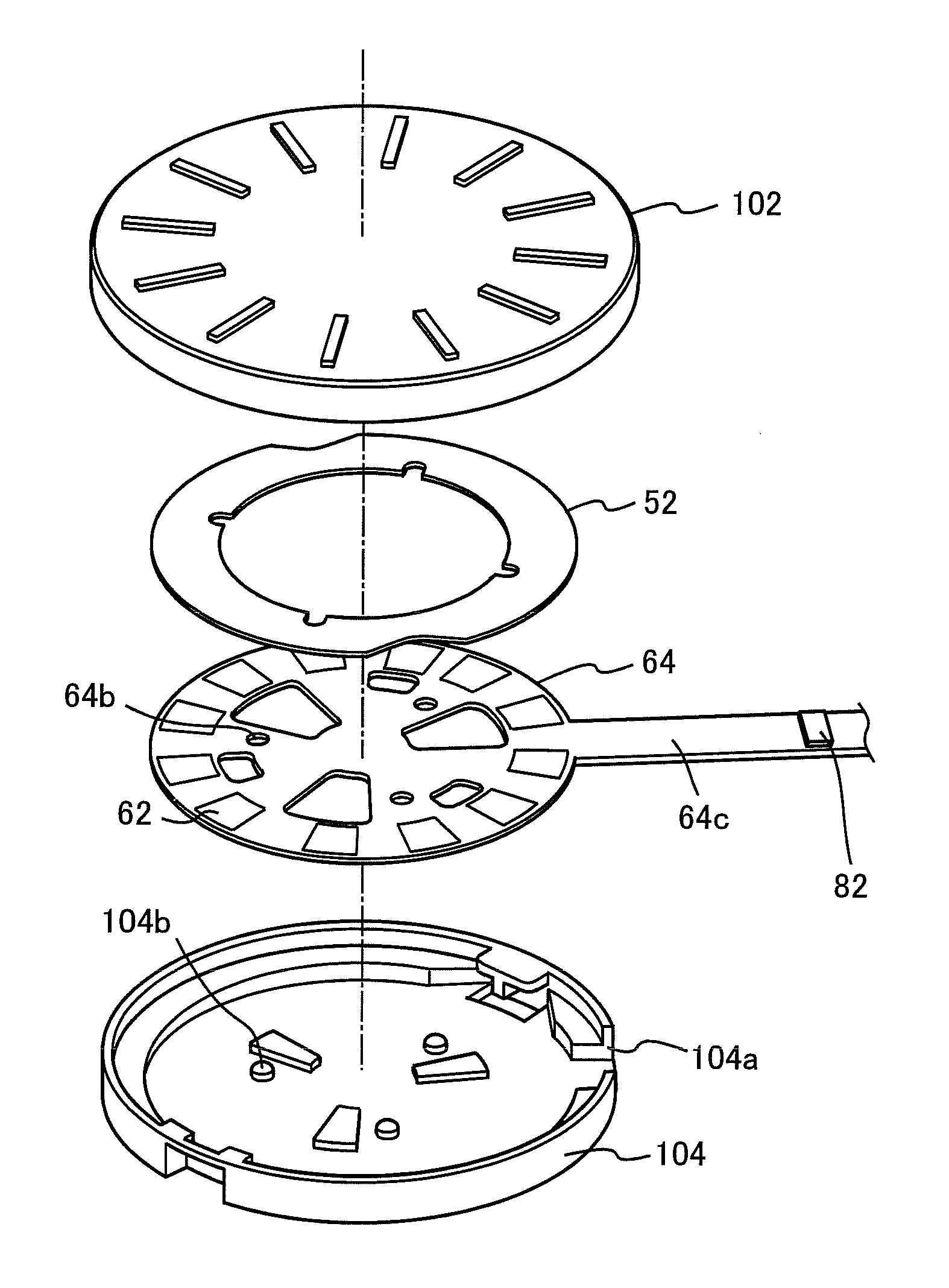
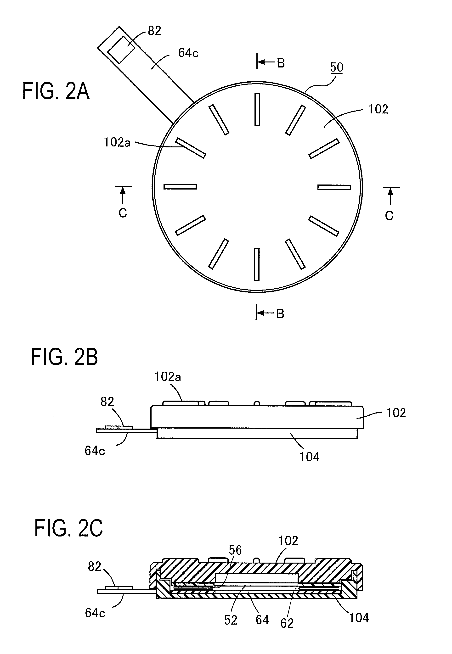
[0107]FIGS. 2A, 2B and 2C are a top plan view of a first embodiment of a rotary input device 50 according to the present invention, its side view, and a sectional view taken along the line C-C, respectively, and FIG. 3 is its exploded perspective view. The rotary input device 50 comprises: an open-topped, shallow cylindrical dish-like casing 104; and a cylindrical lid-like rotary member 102 that is put on the casing 104 from above. The casing 104 and the rotary member 102 are adapted to be able to make sliding contact with each other. On the top surface of the rotary member 102 there are formed radially a plurality of ridges 102a; and the rotary member 102 can easily be turned by pressing its top surface with the ridges formed thereon, for example, with a finger.

[0108]A circular phase electrode holding plate 64 is fixed, as by adhesive, to the bottom of the casing 104. At that time, a plurality of positioning lugs 104b formed on the bottom of the casing 104 and a plurality of positi...

fourth modification

[0155]FIG. 17 illustrates unitary-structured equally-spaced electrodes 56A′ to 56L′ formed by increasing the radial widths of the first equally-spaced electrodes 56A to 56L and the second equally-spaced electrodes 56M to 56X in the Third Modification shown in FIG. 15, so that their opposing circular arcs overlap with each other. The phase electrodes corresponding to the equally-spaced electrodes 56A′ to 56L′ may be those shown in FIG. 16. This modification also produces the same effects as are obtainable with First Embodiment.

fifth modification

[0156]Third Modification, shown in FIGS. 14 and 15, has been described as having a configuration wherein the first equally-spaced electrodes 56A to 56L and the second equally-spaced electrodes 56M to 56X are arranged flush with each other, and the a-phase electrodes 62A to 62F, 62M to 62R and the b-phase electrodes 62G to 62L, 62S to 62X are arranged flush with each other. But these four electrode arrangements may be located all in different planes. The Fifth Modification shown in FIG. 18 is an example of such a configuration.

[0157]The modification depicted in FIG. 18 can be used as a rotary input device such as a mouse wheel. In the rotary input device, as shown in the sectional view shown in FIG. 18, a disc-like rotary member 102 having a rotary shaft 102C is received between casing side walls 104A and 104B, the rotary shaft 102C being rotatably supported by bearing holes 104c made in the interior wall surface of the casing side walls 104A and 104B. The outer periphery of the rota...


PUM


Abstract

Disclosed is a device for accurately detecting the direction and angle of rotation independently of ambient environments. The device is provided with an equally-spaced electrode holding plate 52 having equally-spaced electrodes 56 arranged along the circumference of a first circle, and a fixed phase electrode holding plate having α a-phase electrodes and β b-phase electrodes both arranged along the circumference of a second circle opposite the first circle, wherein when α is equal to or greater than 2, two arbitrary ones of the a-phase electrodes are at positions displaced an angle of an integral multiple of 2π / N apart on the circumference of the second circle in the rotation direction. When β is equal to or greater than 2, two arbitrary ones of the b-phase electrodes are at positions displaced an angle of an integral multiple of 2π / N apart on the circumference of the second circle in the rotation direction. The phase electrodes are arranged so that the a-phase electrodes and the b-phase electrodes are not displaced an angle of an integral multiple of π / N on the circumference of the second circle in the rotation direction.

Description

TECHNICAL FIELD[0001]The present invention relates to a rotary-type input device and, more particularly, to a rotary input device capable of inputting therethrough rotation information and a revolution sensor using the same.BACKGROUND ART[0002]FIG. 1A is an exploded perspective view of a conventional rotary input device 2, and FIG. 1B is a sectional view taken along the line B-B in FIG. 1A. A disc-like rotary member 7 is formed of an insulator, and a user can turn smoothly the rotary member 7 with his finger 3 lightly held on the top of the disc-like rotary member 7. The conventional rotary input device 2 is capable of sensing the angle of rotation of the rotary member 7 caused by the finger 3.[0003]In one part of a casing 4 shown in FIG. 1B, there is formed an operation region 2A sinking in a direction perpendicular to the rotary member 7 and (which direction will hereinafter be referred to as z-direction). In the operation region 2A there are formed recesses 8, for example, at eig...

Claims


Application Information

Patent Timeline
Patent Type & Authority Patents(United States)
IPC IPC(8): H03M11/00G06F3/033G06F3/0362
CPCG06F3/0202G06F3/023H01H25/041H01H2239/006G01D5/245H01H19/00H01H36/00
Inventor SHIMIZU, MASATOTOYOTA, NAOKITSUDUKI, SHIRO
Owner HOSIDEN CORP
Why Eureka
Try Eureka