
Electrical system, and electrical switching apparatus and shutter assembly therefor

a technology of electrical switching apparatus and shutter assembly, which is applied in the direction of air-break switch, switchgear with withdrawable carriage, bus-bar/wiring layout, etc., can solve the problem of limited space available in the circuit breaker compartment to provid

Active Publication Date: 2012-12-11
EATON INTELLIGENT POWER LTD
View PDF7 Cites 9 Cited by
  • Summary
  • Abstract
  • Description
  • Claims
  • Application Information

AI Technical Summary

Benefits of technology

The disclosed concept is a shutter assembly for an electrical switching apparatus, such as a circuit breaker, which can isolate and electrically insulate the breaker connections when the circuit breaker is drawn into and out of electrical contact with the electrical bus members of an electrical system. The shutter assembly comprises a flexible insulating member that can move between a first position to provide access for the conductors to be coupled to the primary contacts and a second position to isolate and electrically insulate the conductors from the primary contacts. The flexible insulating member can be a scroll with a first drum, a second drum, and an insulating sheet extending between them, which can rotate to move the insulating sheet with respect to the conductors and the primary contacts. The shutter assembly can effectively isolate and electrically insulate the breaker connections while occupying minimal space in the electrical system.

Problems solved by technology

However, there is limited space available within the circuit breaker compartment to provide an electrically insulating or isolating mechanism.

Method used


Image

  • Electrical system, and electrical switching apparatus and shutter assembly therefor
  • Electrical system, and electrical switching apparatus and shutter assembly therefor
  • Electrical system, and electrical switching apparatus and shutter assembly therefor

Examples


Embodiment Construction

[0020]Directional phrases used herein, such as, for example, inward, outward, up, down, top, bottom, clockwise, counterclockwise and derivatives thereof, relate to the orientation of the elements shown in the drawings and are not limiting upon the claims unless expressly recited therein.

[0021]As employed herein, the statement that two or more parts are “coupled” together shall mean that the parts are joined together either directly or joined through one or more intermediate parts.

[0022]As employed herein, the term “number” shall mean one or an integer greater than one (i.e., a plurality).

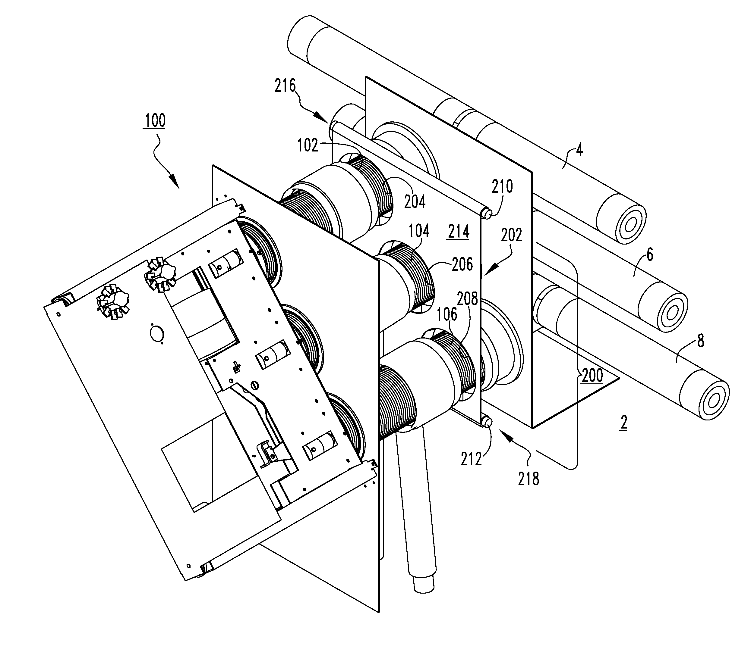
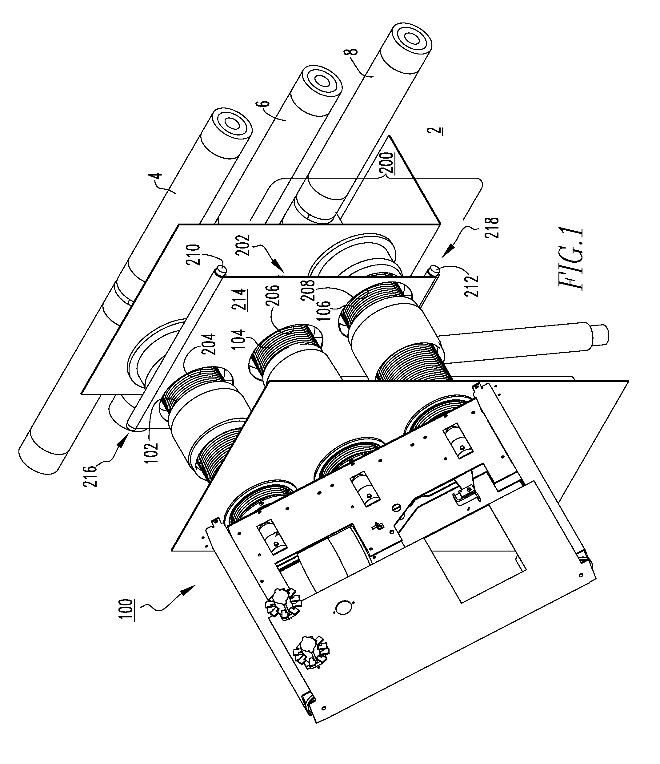
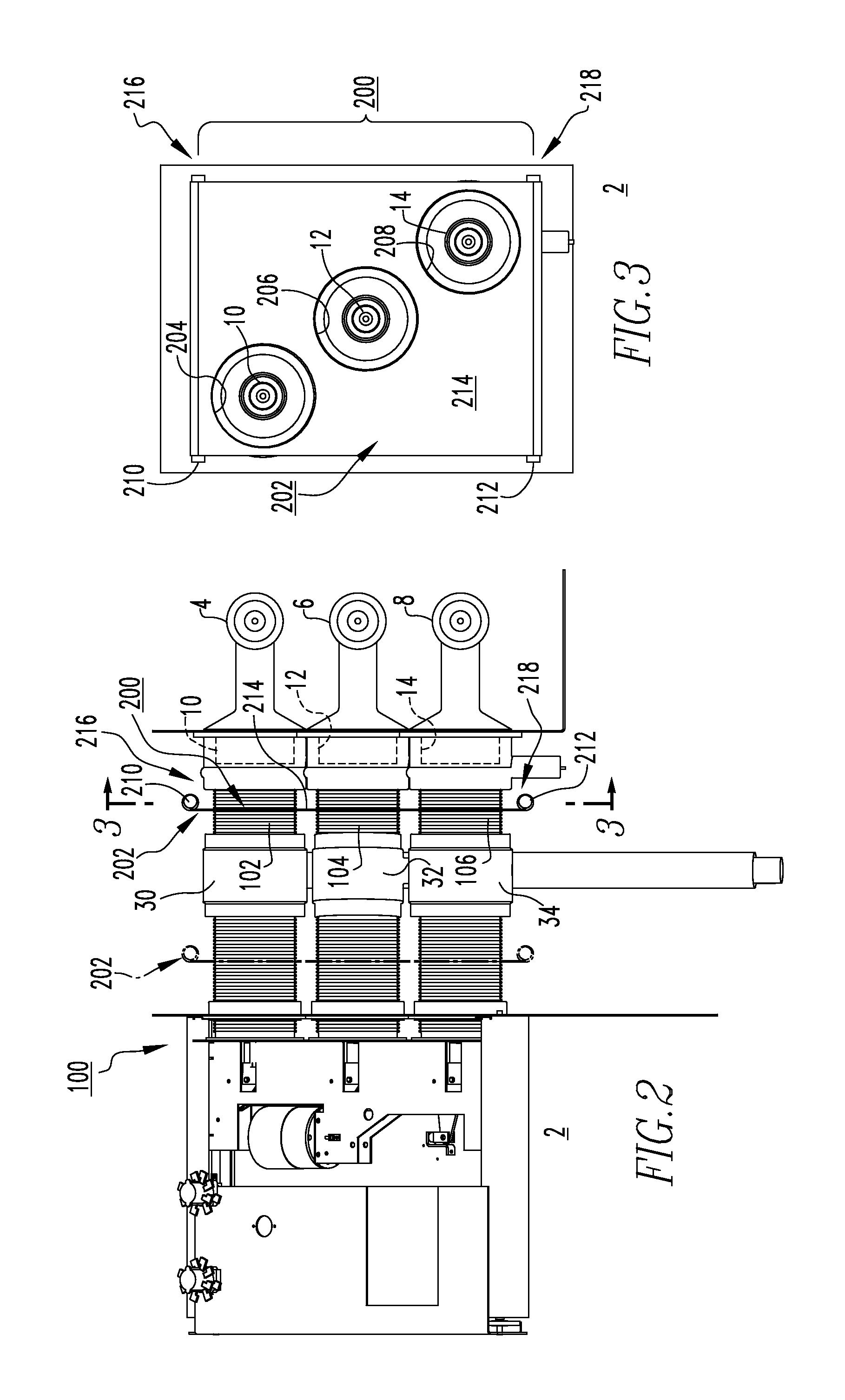
[0023]FIG. 1 shows a shutter assembly 200 for an electrical system 2 (partially shown). The electrical system 2 includes at least one electrical switching apparatus, such as a circuit breaker 100 (partially shown), and a plurality of electrical bus members 4,6,8 (partially shown) having primary contacts 10,12,14 (all shown in hidden line drawing in FIG. 2; see also FIG. 3).

[0024]The circuit breaker ...


PUM


Abstract

A shutter assembly is provided for an electrical system including at least one electrical switching apparatus, such as a circuit breaker, and a plurality of electrical bus members, and a plurality of electrical cable members, and a ground member with a plurality of contacts. Each of the conductors of the circuit breaker is removably coupled to a corresponding primary contact to electrically connect the circuit breaker to the electrical bus members and to electrically connect the circuit breaker to the electrical cable members and to electrically connect the circuit breaker to the ground members. The shutter assembly includes a flexible insulating member movably disposed between the conductors and the primary contacts. The flexible insulating member moves between a first position in which it provides access for the conductors to be coupled to the primary contacts, and a second position in which the flexible insulating member isolates and electrically insulates the bus member conductors from the primary contacts and the cable member conductors (“disconnected”) or isolates and electrically insulates the cable member conductors from the primary contacts and the ground member (“withdrawn”). An electrical switching apparatus and an electrical system employing the shutter assembly are also disclosed.

Description

BACKGROUND[0001]1. Field[0002]The disclosed concept relates generally to electrical systems and, more particularly, to electrical systems employing electrical switching apparatus. The disclosed concept also relates to electrical switching apparatus, such as circuit breakers. The disclosed concept further relates to shutter assemblies for circuit breakers.[0003]2. Background Information[0004]Electrical apparatus, such as electrical switching apparatus used in power distribution systems, are often mounted within a switchgear enclosure (e.g., without limitation, a panelboard; a load center; a meter breaker panel) either individually or in combination with other electrical meters or switchgear (e.g., without limitation, circuit switching devices and circuit interrupters such as circuit breakers, contactors, motor starters, motor controllers and other load controllers).[0005]The electrical enclosure is typically coupled to and supported by a structure such as, for example, a cabinet or a...

Claims


Application Information

Patent Timeline
Patent Type & Authority Patents(United States)
IPC IPC(8): H02B1/20H01H9/00
CPCH02B11/24
Inventor ABRAHAMSEN, MICHAEL HOWARDBEAVER, JON CHRISTOPHERVENKER, DAVID ANDREWROBIRDS, TIMOTHY GORDON
Owner EATON INTELLIGENT POWER LTD
Learn More