Receiver having a gain-controllable input stage

a gain control and input stage technology, applied in the field of receivers with gain controllable input stages, can solve the problems of reducing the extent to which the subsequent stages contribute to the overall receiver noise, affecting the reception quality, so as to achieve an acceptable signal-to-noise ratio, less attenuation, and reduced attenuation within the input stage

Inactive Publication Date: 2012-12-11
NXP BV
View PDF22 Cites 0 Cited by
  • Summary
  • Abstract
  • Description
  • Claims
  • Application Information

AI Technical Summary

Benefits of technology

[0005]It may happen that reception signals are relatively weak. In order to achieve an acceptable signal-to-noise ratio, the attenuation within the input stage can be reduced. There is less attenuation under weak-signal conditions than under typical, strong-signal conditions. The attenuation can be reduced to a point where the input stage provides some signal gain. This signal gain reduces the extent to which the subsequent stages contribute to overall receiver noise. The subsequent stages will play a relatively modest role in terms of noise. The input stage will play a relatively important role in terms of noise. That is, the input stage will substantially determine overall receiver noise when there is little attenuation within the input stage or even no attenuation at all.
[0008]Accordingly, the input transistor can have a low-noise biasing when there is relatively little attenuation, which will be the case under weak-signal conditions. This does not prevent the input transistor from having a strong-signal biasing when there is relatively much attenuation, which will be the case under strong-signal conditions. For those reasons, the invention allows an improved low-noise operation, which contributes to relatively good receiver sensitivity.

Problems solved by technology

There is a risk that subsequent stages receive signals that are so strong that these subsequent stages introduce distortion and, as a result, degrade reception quality.
It may happen that reception signals are relatively weak.
This signal gain reduces the extent to which the subsequent stages contribute to overall receiver noise.
Consequently, an input stage, which has been designed to provide satisfactory performance under these typical conditions, may produce relatively much noise.

Method used


Image

  • Receiver having a gain-controllable input stage
  • Receiver having a gain-controllable input stage
  • Receiver having a gain-controllable input stage

Examples


Embodiment Construction

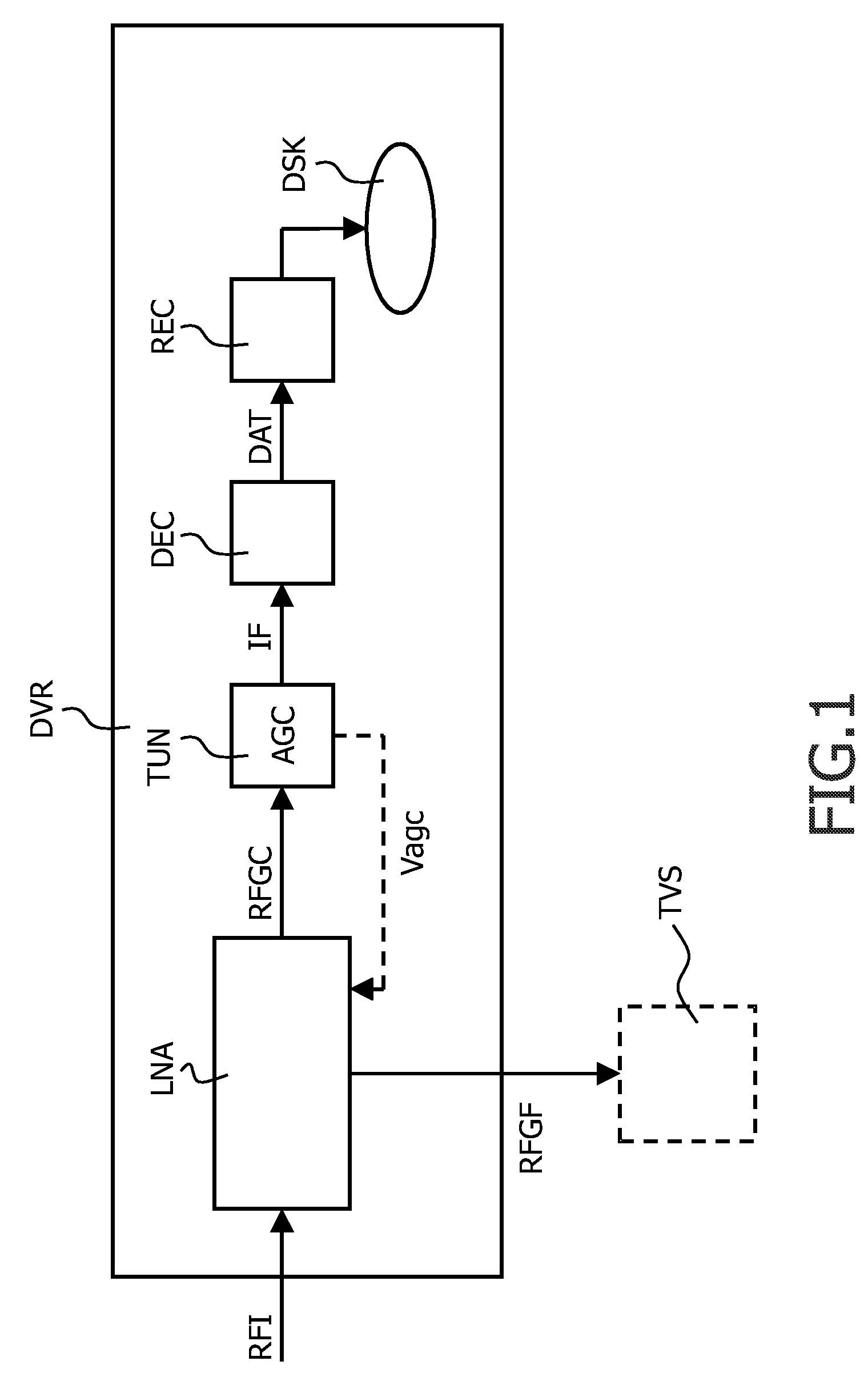
[0012]FIG. 1 illustrates a digital-video recorder DVR, such as, for example, a digital versatile disk (DVD) recorder or a hard disk drive (HDD) recorder, or a combination of both. The digital-video recorder DVR may be comprised in, for example, a so-called set-top box for a cable network. The digital-video recorder DVR will typically have a mains supply.

[0013]The digital-video recorder DVR selects a desired signal present within a radiofrequency spectrum RFI received an input. The desired signal conveys data. The digital-video recorder DVR records this data on a disk. The digital-video recorder DVR may be coupled to a television set TVS, which is illustrated by means of broken lines, or any other type of receiver.

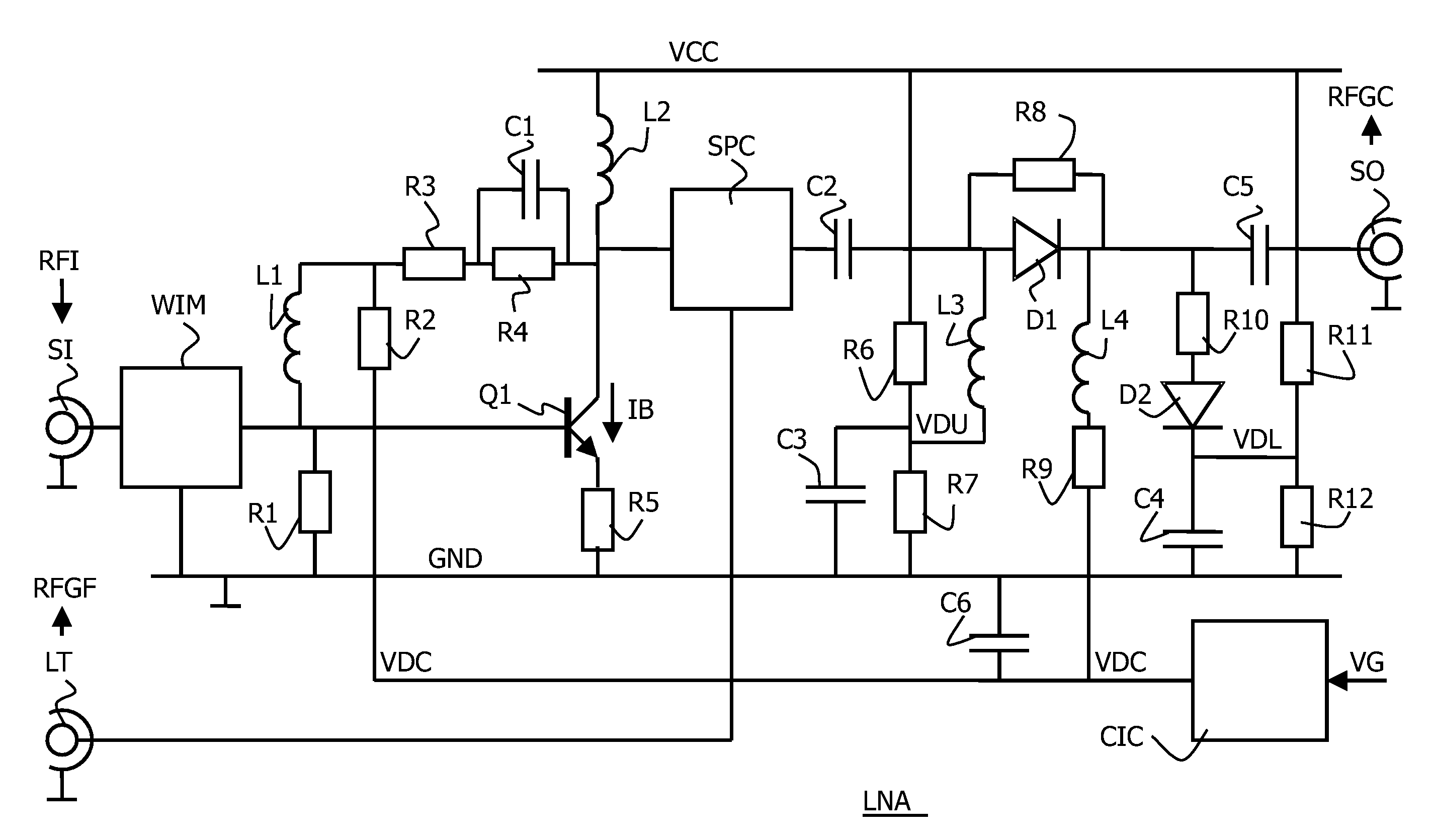
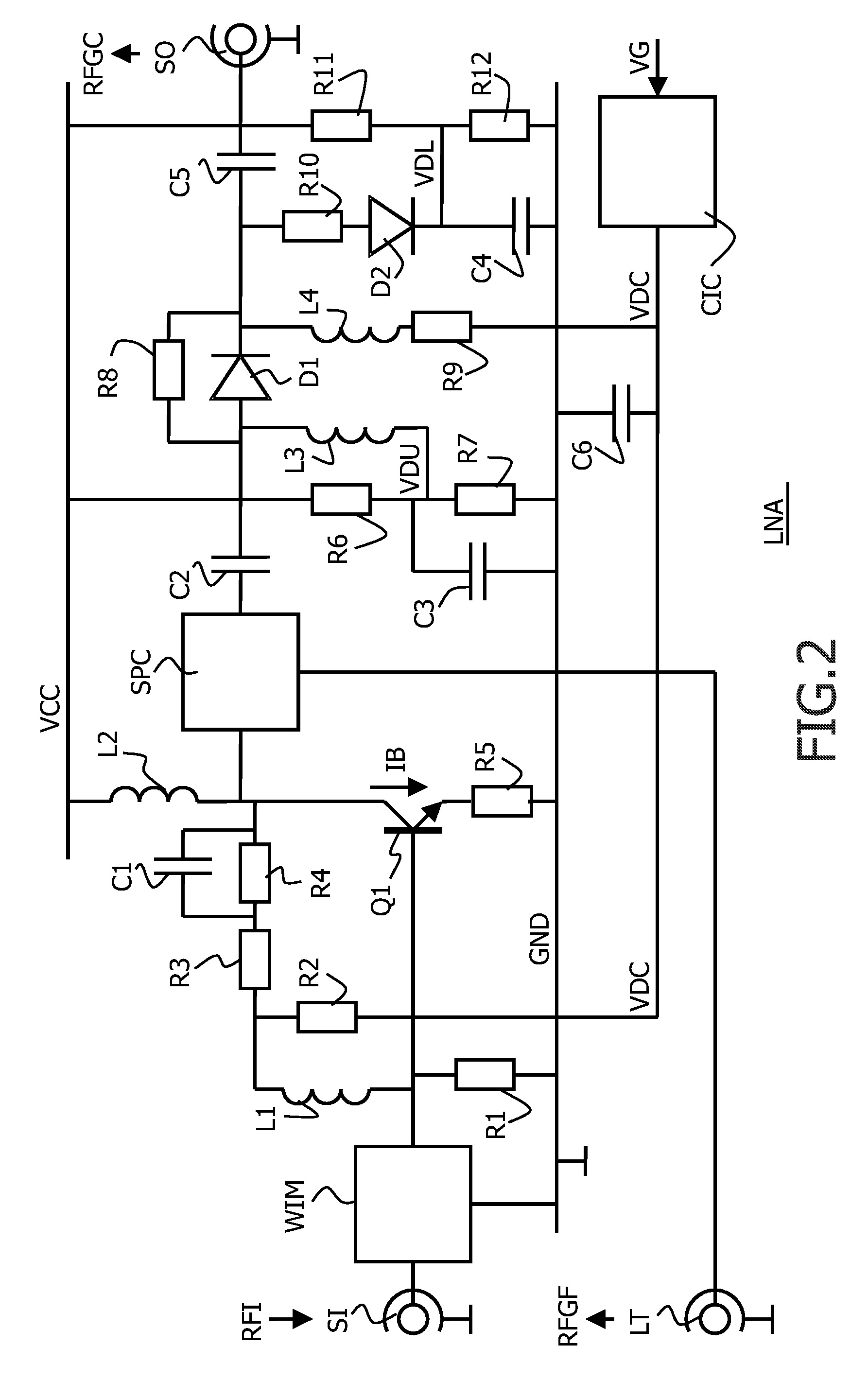
[0014]The digital-video recorder DVR comprises a gain-controllable input stage LNA, a tuner TUN, a decoder DEC, and a recorder REC. The gain-controllable input stage LNA amplifies the radiofrequency spectrum RF. The gain-controllable input stage LNA provides two output sign...


PUM


Abstract

A receiver has an input stage (LNA) that comprises, in a signal direction from an input (SI) to an output (SO), an input transistor (Q1) and an attenuator (D1, D2, R7-R12, C2-C5). The attenuator provides an attenuation that depends on a control signal (VDC). The input stage comprises a transistor-biasing circuit (R2) that biases the input transistor in dependence on the control signal.

Description

FIELD OF THE INVENTION[0001]An aspect of the invention relates to a receiver that has a gain-controllable input stage. The receiver may be, for example, a digital-video recorder that can be coupled to a cable network via which a plurality of channels is transmitted to user homes. In such a digital-video recorder, the gain-controllable input stage typically transfers the plurality of channels to a tuner, which allows selection of a particular channel. Another aspect of the invention relates to a method of operating a receiver.BACKGROUND OF THE INVENTION[0002]U.S. Pat. No. 5,706,060 describes a video recorder with an RF receiving section that receives an antenna signal. The RF receiving section includes wideband amplifiers, which are connected to inductances. One wideband amplifier constitutes an input amplifier for the RF receiver section. Another wideband amplifier constitutes a signal path that loops through the antenna signal to a television receiver.SUMMARY OF THE INVENTION[0003]...

Claims


Application Information

Patent Timeline
Patent Type & Authority Patents(United States)
IPC IPC(8): H04B1/06
CPCH03F1/302H03F1/32H03F2200/211H03F2200/294H03F2200/36H03F2200/372
Inventor TSILIOUKAS, EFTHIMIOS
Owner NXP BV
Why Eureka
Try Eureka