Roundness measuring apparatus

a measuring apparatus and roundness technology, applied in the direction of measuring devices, mechanical measuring arrangements, instruments, etc., can solve the problems of affecting the accuracy of measurement work

Active Publication Date: 2012-12-25
MITUTOYO CORP
View PDF14 Cites 15 Cited by
  • Summary
  • Abstract
  • Description
  • Claims
  • Application Information

AI Technical Summary

Benefits of technology

[0008]An advantage of some aspects of the invention is to provide a roundness measuring apparatus that is capable of changing a stylus automatically without restriction on a measurement region.
[0010]With such a configuration, when a measurement command is given, the detector driving mechanism performs driving operation to bring the stylus of the detector into contact with the measurement target object. The turntable is driven for rotation in a state in which the stylus is in contact with the measurement target object. By this means, measurement of the roundness, or the like, of the measurement target object is carried out. When a stylus replacement command is given, the detector driving mechanism performs driving operation to carry out stylus replacement operation between the detector main unit and the stylus stocker. Therefore, if it is programmed that a stylus replacement command should be issued depending on the shape of a measurement site of the measurement target object, stylus replacement operation is carried out automatically between the detector main unit and the stylus stocker, which makes it possible to conduct measurement work continuously without interruption. Thus, a burden placed on a person who carries out measurement can be reduced. In addition, it is possible to increase the efficiency of measurement work. The stylus stocker is provided outside the measurement region, which is determined on the basis of the operation range of the turntable and the detector driving mechanism. In addition, the detector driving mechanism is configured to be able to move the detector to the outside of the measurement region. Therefore, the stylus stocker does not impose limitations on the measurement region.
[0012]In such a preferred configuration, the detector driving mechanism includes the second slide driving mechanism, which is provided at the tip of the sliding arm and applies a driving force to the detector so as to slide the detector in the direction orthogonal to the sliding axis of the sliding arm, and the swiveling drive mechanism, which moves the second slide driving mechanism in a swiveling direction with the sliding axis of the sliding arm being the center of the swiveling movement of the second slide driving mechanism. The swiveling drive mechanism performs driving operation to turn the second slide driving mechanism by ninety degrees around the sliding axis of the sliding arm, thereby putting the detector into a horizontal position first. Thereafter, the second slide driving mechanism performs driving operation to slide the detector in the direction orthogonal to the sliding axis of the sliding arm. As a result, the detector is moved to the position of the stylus stocker, which is provided outside the measurement region. Therefore, the detector has access to the stylus stocker provided outside the measurement region with a comparatively simple configuration without obstructing roundness measurement operation.

Problems solved by technology

Therefore, it involves considerable downtime in measurement work, that is, a long time period throughout which measurement work has to be stopped.
In addition, the burden of manual stylus removal and attachment that is placed on the person who carries out measurement is not light.
However, if a stylus stock unit that stores plural types of styli is provided on a roundness measuring apparatus, a measurement region will be very restricted because it is necessary to provide the stylus stock unit over a turntable, which constitutes the measurement region.

Method used


Image

  • Roundness measuring apparatus
  • Roundness measuring apparatus
  • Roundness measuring apparatus

Examples


Embodiment Construction

Configuration of Roundness Measuring Apparatus

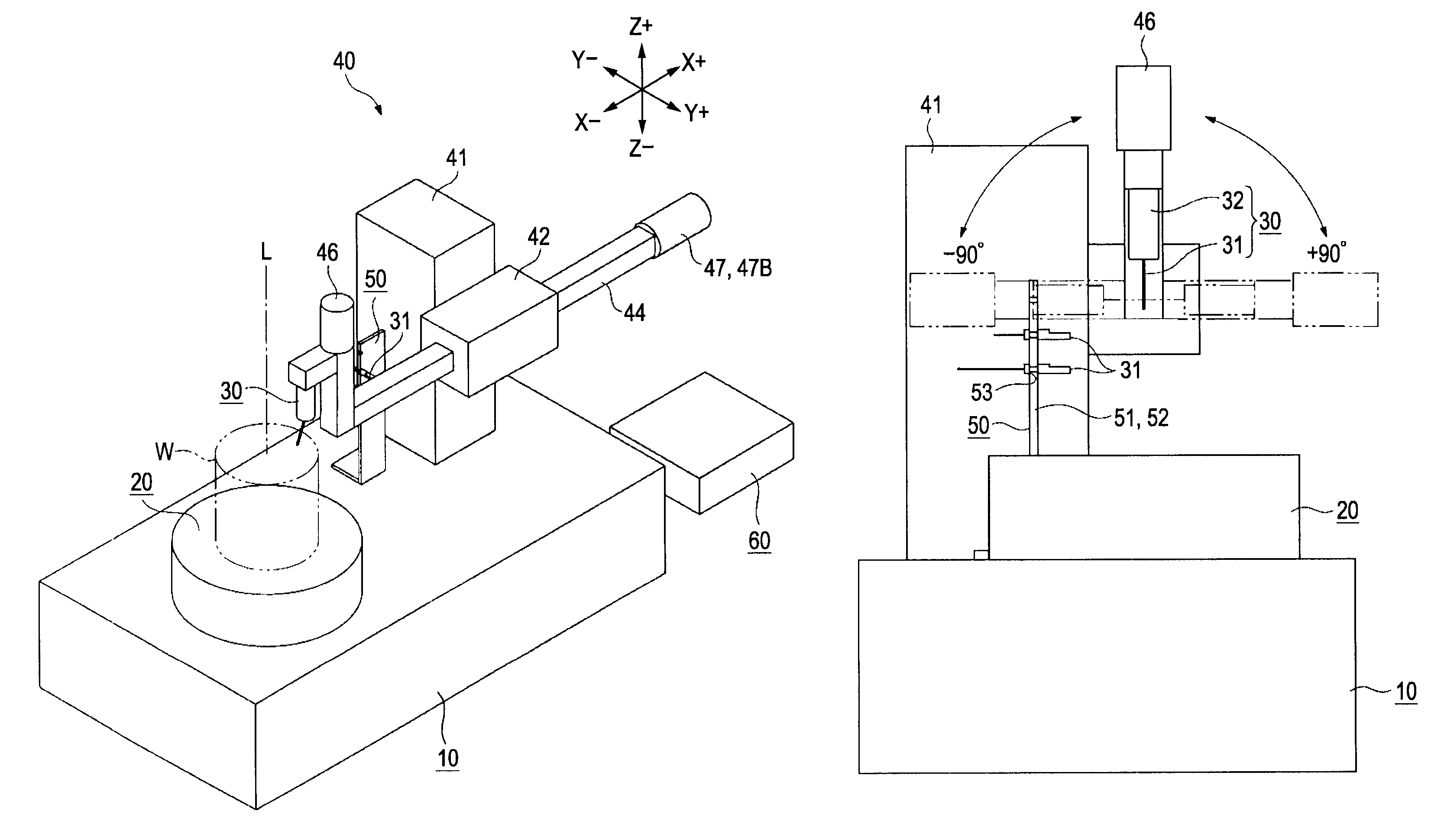
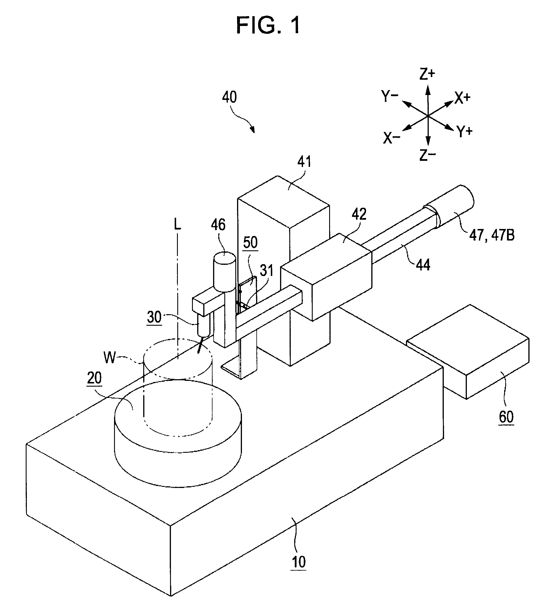
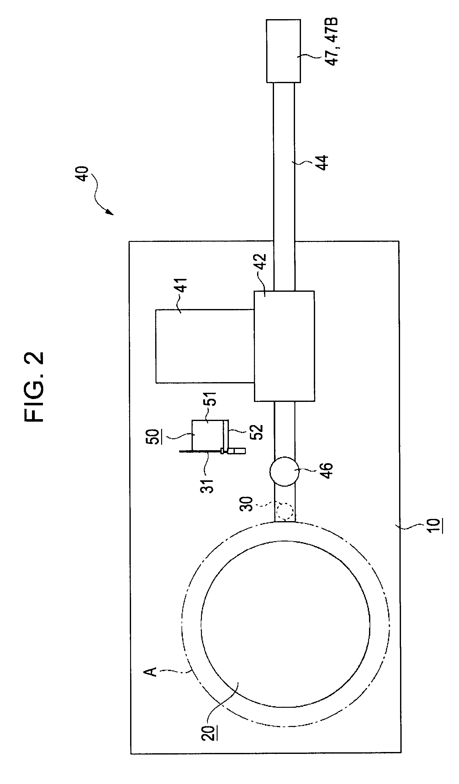
[0023]FIG. 1 is a perspective view that schematically illustrates an example of the configuration of a roundness measuring apparatus according to an exemplary embodiment of the invention. FIG. 2 is a plan view that schematically illustrates an example of the configuration of the roundness measuring apparatus. As illustrated in these drawings, a roundness measuring apparatus according to the present embodiment of the invention is provided with a base 10, a turntable (i.e., turntable) 20, a detector 30, a detector driving mechanism 40, a stylus stock unit 50, and a control unit 60. The turntable 20 is provided on the base 10 at one side thereof. The turntable 20 can rotate around a vertical axis L. A measurement target object (e.g., work piece) W is placed on the upper surface of the turntable 20. The detector driving mechanism 40 applies a driving force to the detector 30. When driven by the detector driving mechanism 40, the detector 30 ...


PUM


Abstract

A roundness measuring apparatus includes a stylus stocker and a controller. The stylus stocker stores plural types of styli prepared corresponding to shapes of measurement sites of a measurement target object. The stylus stocker can store styli in such a manner that each stylus can be held thereon and taken out thereof. The stylus stocker is provided outside a measurement region, which is determined on the basis of the operation range of a turntable and a detector driving mechanism. The detector driving mechanism can move the detector to the outside of the measurement region. When a measurement command is given, the controller carries out roundness measurement of the object while controlling the turntable and the detector driving mechanism. When a stylus replacement command is given, the controller carries out stylus replacement operation between a detector main unit and the stylus stocker while controlling the detector driving mechanism.

Description

BACKGROUND OF THE INVENTION[0001]1. Field of the Invention[0002]The present invention relates to a roundness measuring apparatus. In particular, the invention relates to a roundness measuring apparatus that is capable of changing a stylus automatically.[0003]2. Description of the Related Art[0004]A roundness measuring apparatus is known as an instrument for measuring the roundness of a measurement target object. A roundness measuring apparatus is provided with a base, a turntable, a column, an elevation slider, a sliding arm, and a detector. The turntable is provided on the base. The turntable can rotate around a vertical axis. A measurement target object is placed on the upper surface of the turntable. The column stands on the base. The elevation slider can move upward and downward along the column. The sliding arm is provided on the elevation slider. The sliding arm can slide in the direction orthogonal to the vertical axis. The detector is mounted at the tip of the sliding arm. T...

Claims


Application Information

Patent Timeline
Patent Type & Authority Patents(United States)
IPC IPC(8): G01B5/004
CPCG01B21/047G01B5/201
Inventor NAKAYAMA, TATSUKISHINDO, HIDEKI
Owner MITUTOYO CORP
Why Eureka
Try Eureka