Industrial robot space pose precision test system

An industrial robot, precision testing technology, applied in manipulators, manufacturing tools, etc., can solve the problems of inability to measure the spatial attitude accuracy of the robot end, inability to fully evaluate the robot accuracy index, five-point test evaluation test system, etc., to achieve measurement efficiency. High, simple structure, low cost effect

Pending Publication Date: 2021-06-08
SHENYANG INST OF AUTOMATION - CHINESE ACAD OF SCI
View PDF8 Cites 4 Cited by
  • Summary
  • Abstract
  • Description
  • Claims
  • Application Information

AI Technical Summary

Problems solved by technology

At present, the test mainly uses a high-precision laser tracker for measurement, but the cost of the laser tracker is relatively high, the operation is more complicated, and the measurement of attitude accuracy requires additional sensors. Most companies do not have the ability to purchase this set of equipment
[0003] Most of the current test systems only measure the spatial position accuracy of the robot end, but cannot measure the spatial attitude accuracy of the robot end, and cannot fully evaluate the robot’s accuracy indicators
In addition, the Chinese patent CN 105865341A provides a method and equipment for testing the attitude change of the robot end, but it can only measure the accuracy of one point in the space, while the national standard GB / T 12642-2013 stipulates that five points in the largest test cube of the robot should be points for evaluation
Among the currently disclosed technologies, there is no test system for testing and evaluating the five points

Method used


Image

  • Industrial robot space pose precision test system
  • Industrial robot space pose precision test system

Examples


Embodiment Construction

[0021] The present invention will be described in further detail below in conjunction with the accompanying drawings.

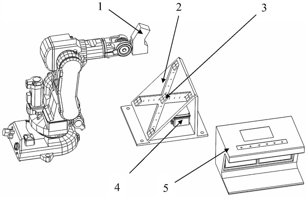
[0022] The invention provides an industrial robot space pose accuracy test system, such as figure 1 shown. The test system includes a pose measurement cube assembly 2, a measurement target 3, a visual sensor 1 and a power supply module 4; the visual sensor 1 is fixed at the end of an industrial robot, and the visual sensor 1 is connected to a terminal controller through a transmission cable, and the terminal control The device is fixed on the console 5. The pose measurement cube assembly 2 is placed in the measurement area of ​​the vision sensor, and the pose measurement cube assembly includes an X-shaped groove 7, and the measurement target 3 is installed in the X-shaped groove.

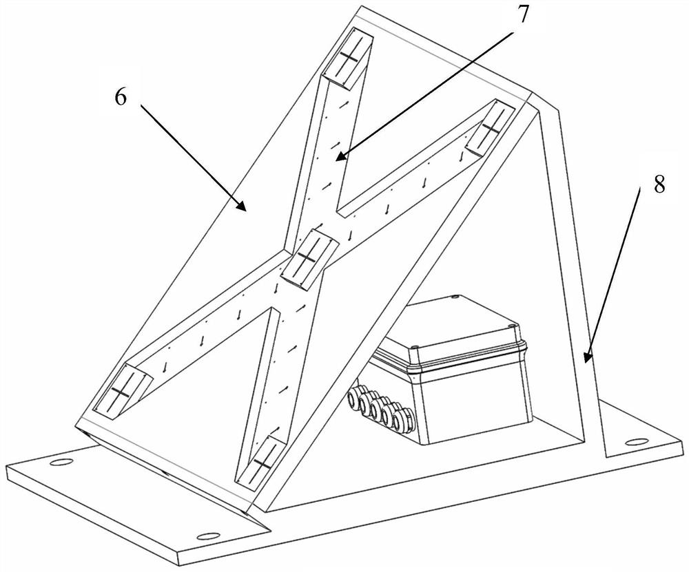
[0023] The pose measurement cube assembly includes a standard test board 6, an X-shaped groove 7 and a mounting bracket 8, the X-shaped groove is opened on the outer surface of t...


PUM


Abstract

The invention discloses an industrial robot space pose precision test system, and belongs to the technical field of industrial robots. The industrial robot space pose precision test system comprises a pose measurement cube assembly, a measurement target, a power supply module, a visual sensor and an operation table. The measurement cube assembly is fixed to the front face of a robot measurement area through bolts. The measurement target is fixed in an X-shaped groove in the surface of a pose measurement cube through a screw, the X-shaped groove is located in the front surface of the pose measurement cube assembly, the total length of the X-shaped groove is 1000 mm, and the requirements of different robot working spaces are met. The power supply module is fixed to the bottom of a base through screws and can supply power to the five measurement targets at the same time; and the visual sensor is fixed to the tail end of a robot and connected with the operation table through a communication cable. The industrial robot space pose precision test system is specially used for testing the space pose precision of the industrial robot, and is convenient to use, high in measurement working efficiency, high in precision and low in cost.

Description

technical field [0001] The invention relates to the technical field of industrial robots, in particular to an industrial robot space pose accuracy test system. Background technique [0002] Spatial pose accuracy is one of the most important performance indicators of industrial robots. At present, the test mainly uses a high-precision laser tracker for measurement, but the cost of the laser tracker is relatively high, the operation is more complicated, and the sensor needs to be purchased to measure the attitude accuracy. Most enterprises do not have the ability to purchase this set of equipment. [0003] At present, most of the test systems only measure the spatial position accuracy of the robot end, but cannot measure the spatial attitude accuracy of the robot end, and cannot fully evaluate the robot's accuracy indicators. In addition, the Chinese patent CN 105865341A provides a method and equipment for testing the attitude change of the robot end, but it can only measure ...

Claims


Application Information

Patent Timeline
Patent Type & Authority Applications(China)
IPC IPC(8): B25J19/00
CPCB25J19/0095
Inventor 李志海于洪鹏吴镇炜吴清潇王恒之欧锦军
Owner SHENYANG INST OF AUTOMATION - CHINESE ACAD OF SCI
Why Eureka
Try Eureka