System for automatically reading a response form using a digital camera

a digital camera and response form technology, applied in the direction of visual presentation using printers, instruments, electromagnetic radiation sensing, etc., can solve the problems of inability to print or reproduce on plain paper, many limitations, and special forms for omr scanners

Active Publication Date: 2012-12-25
GRADECAM
View PDF4 Cites 10 Cited by
  • Summary
  • Abstract
  • Description
  • Claims
  • Application Information

AI Technical Summary

Problems solved by technology

While OMR technology is very valuable, it has many limitations.
The first prominent limitation is that OMR scanners require specially produced forms.
The fact that these forms cannot be printed or reproduced on plain paper makes them very expensive for schools that use them frequently.
Another limitation is that OMR scanners are almost always sheet fed.
Because moving parts are required to feed the forms through these machines, they are typically large, expensive, and require frequent maintenance and cleaning.
While this addresses the limitation of not being able to print forms on plain paper, it does not address many of the other issues that trouble OMR scanners as these newer scanners are also typically sheet fed.
However, the solutions previously offered by the subject inventor came with factors that limit the utility of the invention.
This is due to physical distortion that results with larger forms in addition to optical distortion caused by the lens of the camera when imaging larger areas.
This limitation results in a maximum capacity of a response form that corresponds to roughly twenty questions with four options each (e.g. ‘A’, ‘B’, ‘C’, or ‘D’).
A second limitation is that the layout of the form had to be preprogrammed which does not allow for any flexibility.

Method used


Image

  • System for automatically reading a response form using a digital camera
  • System for automatically reading a response form using a digital camera
  • System for automatically reading a response form using a digital camera

Examples


Embodiment Construction

[0027]Referring more specifically to the drawings, for illustrative purposes the present invention is embodied in the apparatus generally shown in FIG. 1 through FIGS. 10A and 10B. It will be appreciated that the apparatus may vary as to configuration and as to details of the parts, and that the method may vary as to the specific steps and sequence, without departing from the basic concepts as disclosed herein.

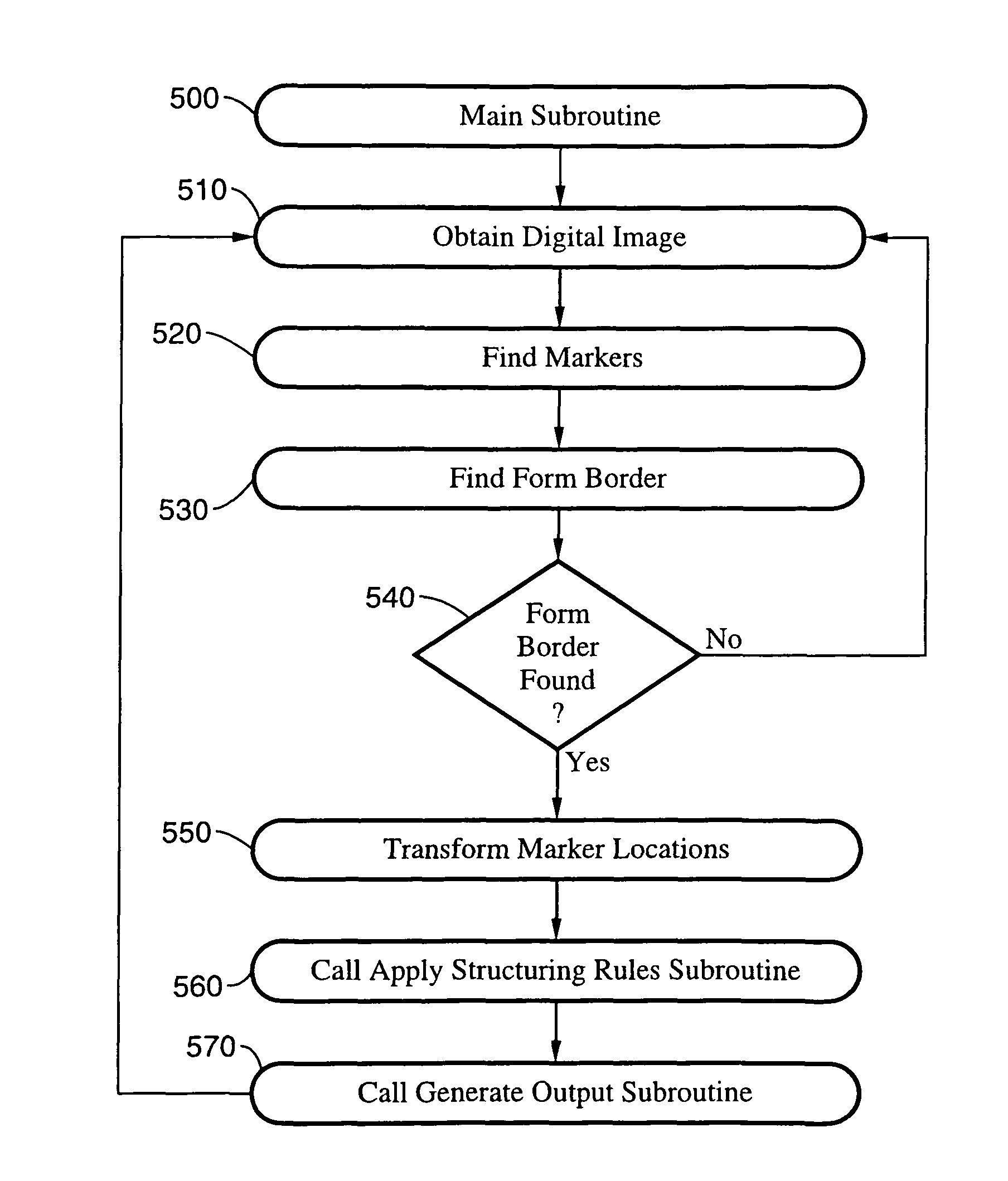
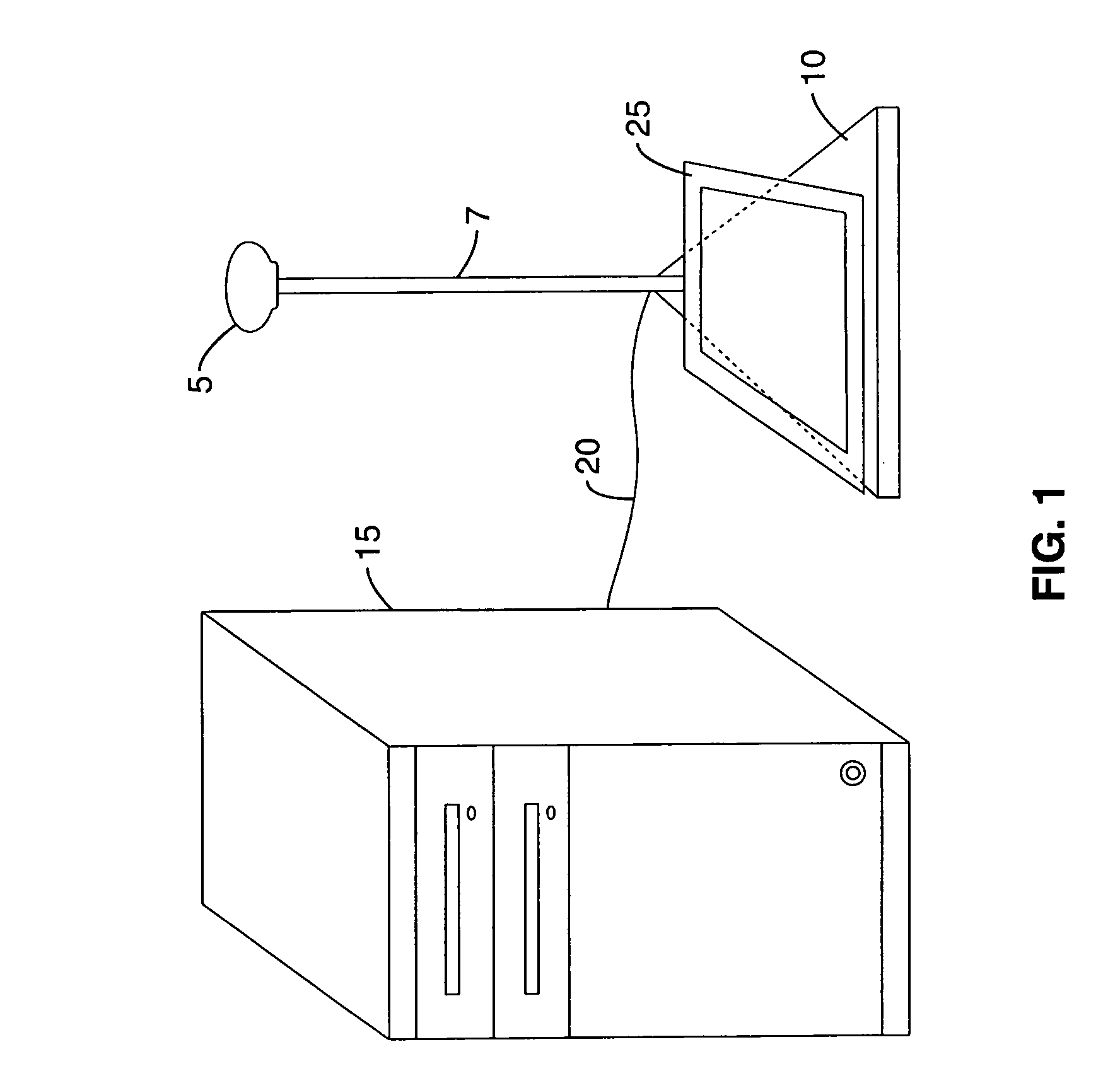
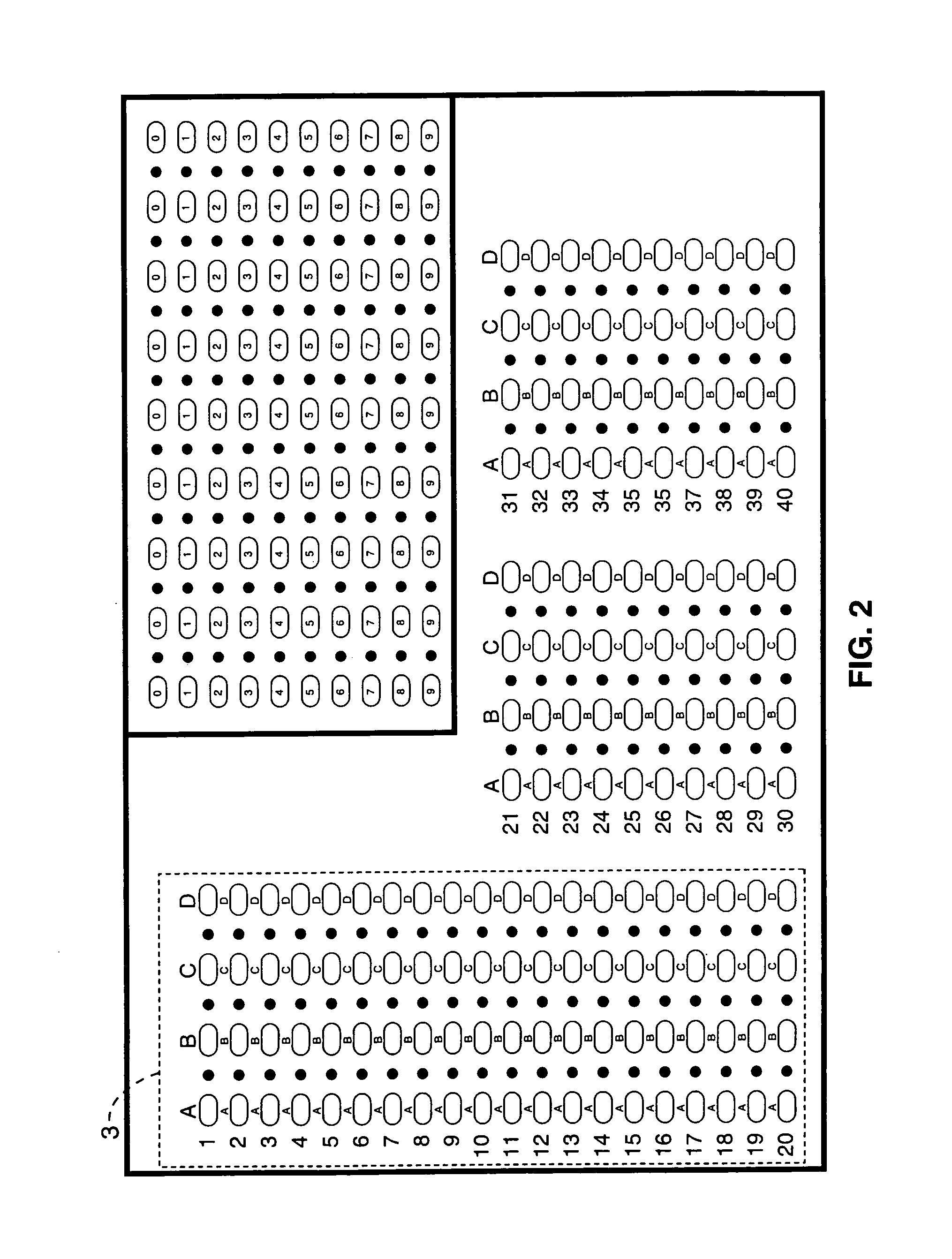
[0028]Again, a preferred embodiment of the invention is a device that comprises three main components: a) a digital camera; b) a computer attached to the digital camera; and c) computer software running on the computer. The subject invention is most easily understood by first understanding how a user interacts with it. Typically a user will use the invention to scan a set of response forms for processing or storage on the computer. In order to accomplish this task the user will typically begin by starting the software on the computer after verifying that the digital camera is ...


PUM


Abstract

A system for automatically reading a response form marked by a user, including the response form containing a structured set of markers and a structured set of response areas, a camera for obtaining a digital image which contains the response form, programming for identifying positions of a majority of the markers within the digital image, programming for using a set of structuring rules in conjunction with the positions of the markers to obtain a structured set of response areas, programming for reading responses located at the response areas, and programming for generating an output of user responses.

Description

CROSS-REFERENCE TO RELATED APPLICATIONS[0001]This application claims priority from U.S. provisional application Ser. No. 60 / 993,207 filed on Sep. 10, 2007.BACKGROUND OF THE INVENTION[0002]1. Field of the Invention[0003]This invention pertains generally to an automatic reading of response forms in order to collect data. More particularly to the automatic reading of response forms for data collection in which a large form is capable of being scanned and the layout of the form is dynamically determined.[0004]2. Description of Related Art[0005]The present invention relates to the automatic reading of response forms in order to collect data. The most prominent example of this field is the use of optical mark reader (OMR) forms and scanners for testing in schools. These OMR forms are given to students for them to record their responses to multiple-choice test questions and then fed through an OMR scanner to score and interpret those responses. OMR technology is not only valuable for multi...

Claims


Application Information

Patent Timeline
Patent Type & Authority Patents(United States)
IPC IPC(8): G06K7/10
CPCG06K9/6253G06K9/00449G06V30/412G06V10/945G06F18/40
Inventor PORTER, ROBERT AUSTIN
Owner GRADECAM
Why Eureka
Try Eureka