Key box construction

a key box and construction technology, applied in the field of key box construction, can solve the problems of inability to store finger rings or the like, inability to meet the needs of operators' hands, and inability to carry a rotary shaft with their hands, so as to facilitate mounting and facilitate storage. , the effect of increasing the breaking strength

Inactive Publication Date: 2013-01-01
KEIDEN SECURITY KIKIHANBAI
View PDF38 Cites 7 Cited by
  • Summary
  • Abstract
  • Description
  • Claims
  • Application Information

AI Technical Summary

Benefits of technology

[0011]According to the key box construction of this invention, an outer cover is provided with grooves each having the same width at an angle which does not allow the outer cover to be taken away at the time of usual opening and closing of the door, thereby making the door construction removable. Furthermore, provision of the hooks at the lower end portion of the door allows, even if the bearing parts are weak, regardless of this, the door, when closed, to be directly hooked on the inner case by means of the hooks and the latch, thereby increasing the breaking strength. Moreover, because of the removable door construction, even when the door or the outer cover is broken, exchange of only the broken parts is possible, and accordingly, inexpensive.
[0012]This invention allows the shackle to be attached and detached in one-touch control by eliminating a course of action in front and behind when the shackle is inserted. This facilitates the mounting on the wall, the door or the like, and in addition, the basic parts (the door, the front outer cover, the front inner case, the key storing tray, the rear inner case, and the rear cover) can be made to serve a double purpose. Moreover, since the shackle is shaped in such a manner that both legs of the shackle are locked by means of the shackle locking lever, a strength higher than that in the past can be secured.
[0013]The key storing tray is included in the key box, so that no omission of a card, a key, a finger ring or the like occurs, and the storing thereof is made easy. Furthermore, in the case where the key storing tray is constructed in such a manner that it has an inclination from the door side towards an operator to the interior at both sides thereof with a width a little narrower than the traversal width of the card, when a card is inserted therein, it naturally falls to the door side towards the operator, and in addition, the above-mentioned construction allows to aim at being easy to store a key, a finger ring or the like, and at securing the storing space to the maximum degree.
[0014]The outer covers are shaped in such a manner that they can be assembled in one-touch control, the front outer cover is shaped in such a manner that when the door is closed, removal of the front outer cover is impossible due to the bearing parts for rotating the door, and the rear outer cover is shaped in such a manner that the provision of holes for inserting the shackle makes removal of the rear outer cover impossible without detaching the shackle.BRIEF EXPLANATION OF THE DRAWINGS
[0015]FIG. 1-1 is a side sectional view showing a state where a door of a key box is closed;
[0016]FIG. 1-2 is a side sectional view showing a state where the door of the key box is opened until a removable position;

Problems solved by technology

However, since the door cannot be taken away from the key box, setting of the numbers, and mounting on the wall or the like are difficult to carry out, and moreover, making the construction which allows the rotary shaft to be removed with an operator's hand, was impossible as viewed in terms of strength.
Furthermore, since a shackle was difficult to detach, and mounting the key box on the wall or the door of a building was troublesome, making it serve a double purpose of a hanging-down type and a wall-mounted type was impossible.
Moreover, when ones like credit cards are stored, there were problems, one being that of such a card leaning on the inner wall so that the card is difficult to take out, and the other being a problem that the card obstructs, so that a key, a finger ring or the like are difficult to store.
Moreover, external appearance, that is, an outer cover in the case of a hanging-down type, is covered with rubber or resin to prevent the object on which the key box is mounted from being damaged; however, this was one which spoils the aesthetic appearance thereof.

Method used


Image

  • Key box construction
  • Key box construction
  • Key box construction

Examples


example 1

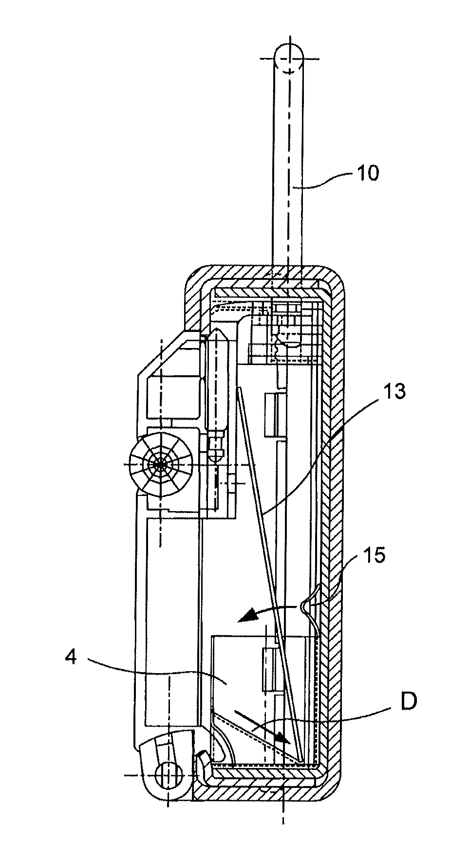
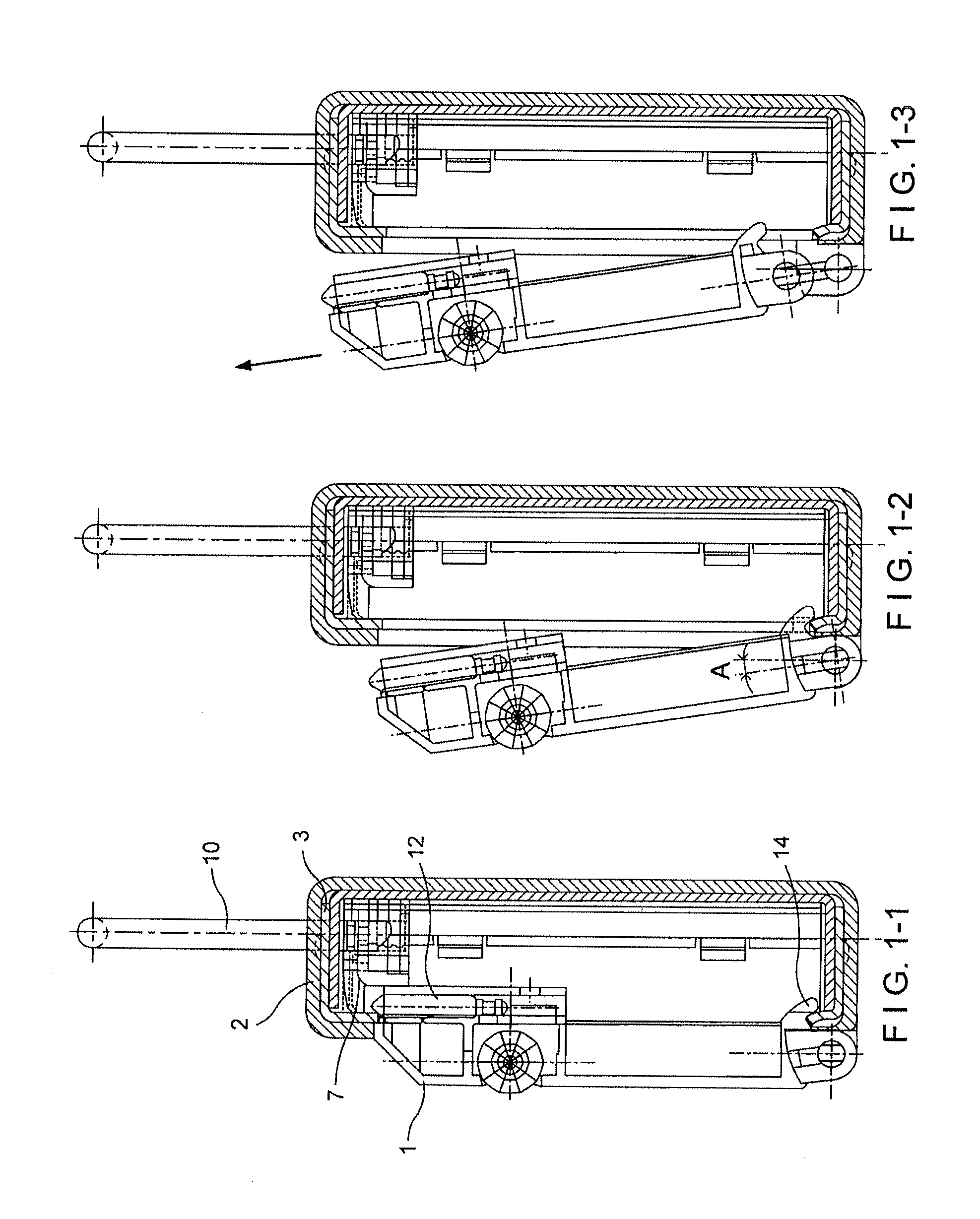
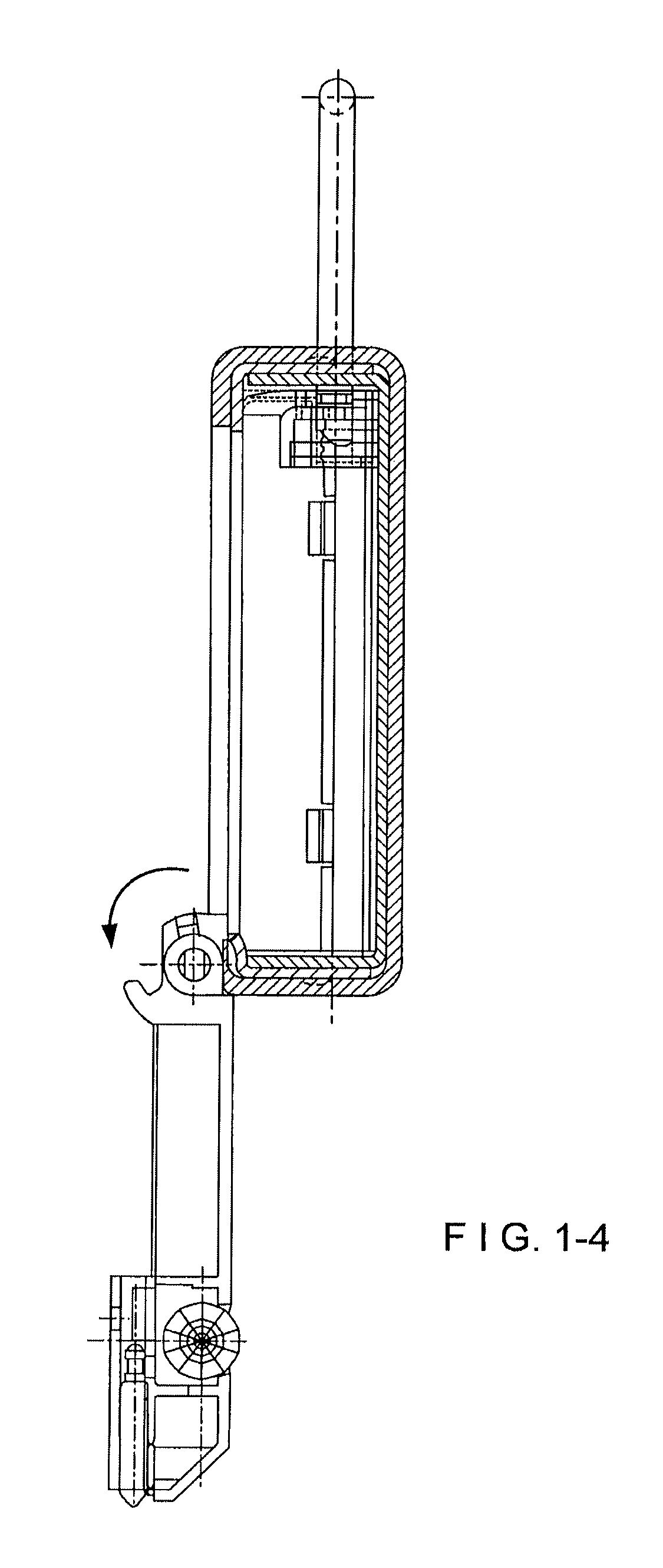
[0040]Referring to FIG. 1, a key box is illustrated from a state where a door 1 is closed (FIG. 1-1) to a state where the door is opened to a removable position (FIG. 1-2), further, by way of a state where the door is pulled out in the arrow-marked direction (FIG. 1-3), and at last until a state where the door is opened to the maximum degree (FIG. 1-4).

[0041]The shaft of the door 1 is provided with two parallel flat surfaces B in the circumferential direction of the shaft (FIG. 3) in the axial extensions of the shaft, and an outer cover 2, which at a hinging end are provided with bearing parts in the form of grooves C each having the same width as the distance between the flat surfaces (FIG. 2) and at an angle A (FIGS. 1-2), thereby enabling the door to be removed. Removal of the door 1 is made possible by providing bearing parts 20 in the outer cover 2 made of resin; however, in that degree, the bearing parts 20 are weak in breaking strength. As a solution strategy thereof, hooks 1...


PUM


Abstract

A key box construction, wherein a shaft of a door is provided with two parallel flat surfaces in axial extensions of the shaft, an outer cover is provided with bearing parts which each comprise a groove having the same width between parallel flat surfaces of the groove as the width between the two parallel flat surfaces of each axial extension and at an angle. The door is provided at the lower end portion thereof with hooks, whereby the door is hooked directly on an inner case by the hooks and a latch.

Description

BACKGROUND[0001]1. Technical Field[0002]This invention relates to a key box construction having a strength which enables any unjust cancellation to be certainly prevented.[0003]2. Background of the Art[0004]An existing dial type key box has a construction, in which two or more dials each having numbers 0:9 are set to determined voluntary figures (a secret code number) to rotate (open) a door. However, since the door cannot be taken away from the key box, setting of the numbers, and mounting on the wall or the like are difficult to carry out, and moreover, making the construction which allows the rotary shaft to be removed with an operator's hand, was impossible as viewed in terms of strength.[0005]Furthermore, since a shackle was difficult to detach, and mounting the key box on the wall or the door of a building was troublesome, making it serve a double purpose of a hanging-down type and a wall-mounted type was impossible. Moreover, when ones like credit cards are stored, there were...

Claims


Application Information

Patent Timeline
Patent Type & Authority Patents(United States)
IPC IPC(8): E05B65/52
CPCE05B19/0005E05B37/025E05B67/22E05B2067/025Y10T70/424Y10T70/426Y10T70/459Y10T70/487Y10T70/489Y10T70/491Y10T70/5031Y10T70/5558Y10T70/5606Y10T70/8676A47G29/10E05B67/063E05D7/1072E05D11/0027
Inventor SAKAI, NOBUYOKATAUMI, YOSHIMASA
Owner KEIDEN SECURITY KIKIHANBAI
Why Eureka
Try Eureka