Composite armor, armor system and vehicle including armor system

a composite armor and armor system technology, applied in the field of composite armor, can solve the problems of high-volume production without significant defects, difficult fabrication of many composite armor structures, and requiring relatively exotic materials

Inactive Publication Date: 2013-01-01
BATTELLE ENERGY ALLIANCE LLC
View PDF23 Cites 7 Cited by
  • Summary
  • Abstract
  • Description
  • Claims
  • Application Information

AI Technical Summary

Problems solved by technology

However, many composite armor structures are somewhat difficult to fabricate, require relatively exotic materials, and may not be susceptible to high-volume production without significant defects.
Thus, there is no capability of deploying such a system for selective protection of personnel from a situation-specific threat posed from a particular direction or directions.

Method used


Image

  • Composite armor, armor system and vehicle including armor system
  • Composite armor, armor system and vehicle including armor system
  • Composite armor, armor system and vehicle including armor system

Examples


Embodiment Construction

[0022]In the description that follows, the same or similar elements and features are identified by like reference numerals for clarity.

[0023]As used herein with respect to an armor panel, the term “outermost” is indicative of the layer or surface of the armor panel to be oriented facing a direction of an incoming threat in the form of, for example, a projectile, fragment or blast or shock wave. Accordingly, there is no requirement that the layer or surface be exposed and, so, the term encompasses a layer or surface of an armor panel that may be covered, by way of non-limiting example, with a fabric, paint, or other cover or coating.

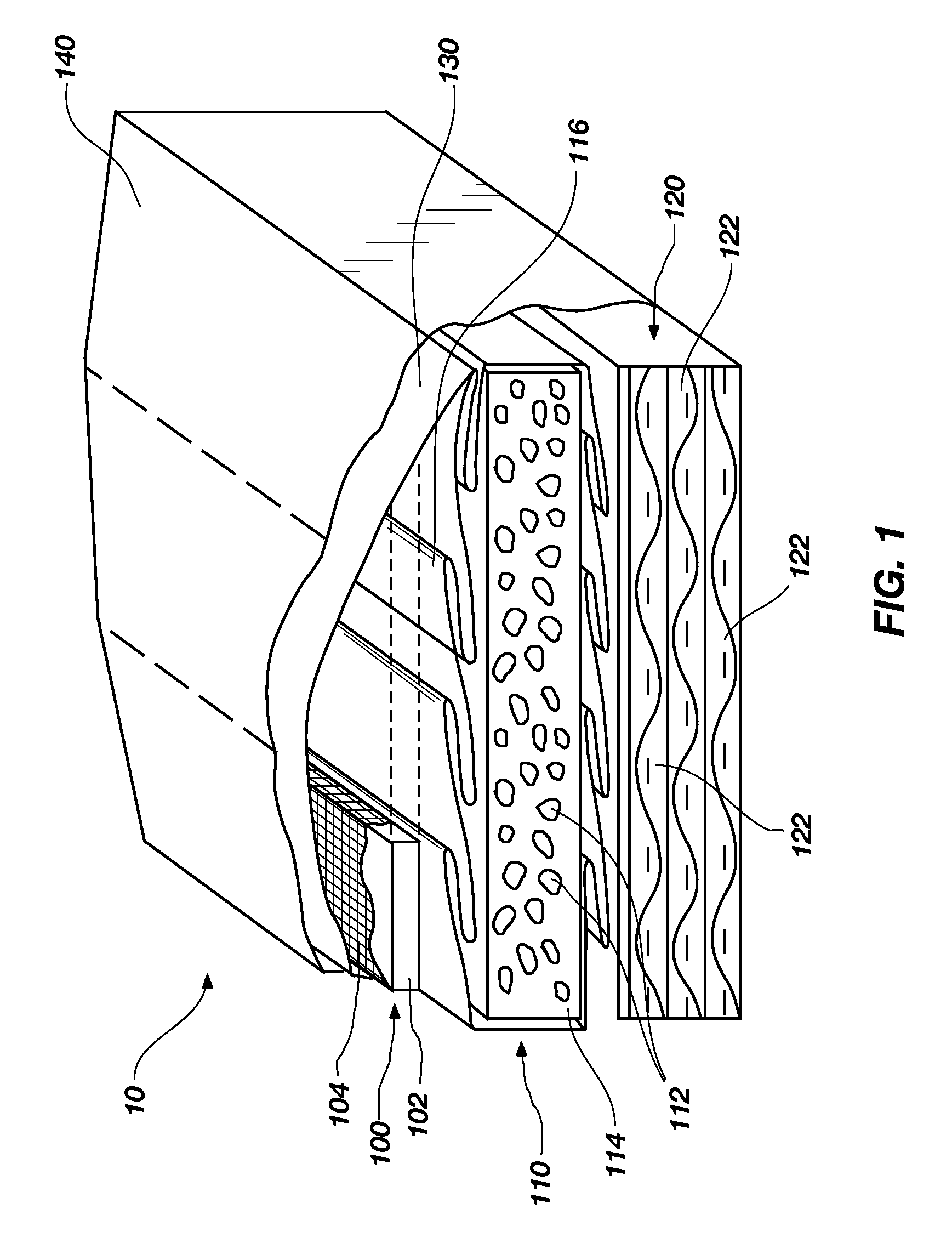
[0024]Referring now to FIG. 1, an embodiment of composite armor panel 10 is depicted. As depicted, composite armor panel 10 comprises a plurality of functional layers serving various functions, in combination with additional components. In one embodiment, armor panel is approximately fifteen to sixteen inches square.

[0025]Outermost functional layer 100 co...


PUM

PropertyMeasurementUnit
densityaaaaaaaaaa
diameteraaaaaaaaaa
diameteraaaaaaaaaa

Abstract

Composite armor panels are disclosed. Each panel comprises a plurality of functional layers comprising at least an outermost layer, an intermediate layer and a base layer. An armor system incorporating armor panels is also disclosed. Armor panels are mounted on carriages movably secured to adjacent rails of a rail system. Each panel may be moved on its associated rail and into partially overlapping relationship with another panel on an adjacent rail for protection against incoming ordnance from various directions. The rail system may be configured as at least a part of a ring, and be disposed about a hatch on a vehicle. Vehicles including an armor system are also disclosed.

Description

CONTRACTUAL ORIGIN OF THE INVENTION[0001]This invention was made with government support under DE-AC07-051D14517 awarded by the United States Department of Energy. The government has certain rights in the invention.TECHNICAL FIELD[0002]The invention relates generally to composite armor. More specifically, embodiments of the invention relate to relatively lightweight composite armor and to a selectively configurable armor system incorporating panels of composite armor, which may, but need not, be of the structure of an embodiment of the lightweight composite armor disclosed and claimed herein. Embodiments of the invention also relate to vehicles including an armor system.BACKGROUND[0003]Composite armor systems for protecting vehicles and personnel against incoming ordnance have been in existence for decades. As used herein, the term “ordnance” includes and encompasses not only inert projectiles from small arms, but also explosive-carrying projectiles, fragments propelled from explosi...

Claims


Application Information

Patent Timeline
Patent Type & Authority Patents(United States)
IPC IPC(8): F41H5/06F41H5/18F41H7/02
CPCF41H5/013F41H5/04F41H5/0428F41H5/0492F41H5/16F41H5/223F41H7/04
Inventor CHU, HENRY S.JONES, WARREN F.LACY, JEFFREY M.THINNES, GARY L.
Owner BATTELLE ENERGY ALLIANCE LLC
Why Eureka
Try Eureka