Sheet coating system on an apparatus for extrusion forming a sheet product

a technology of extrusion forming and coating system, which is applied in the direction of turning machine accessories, butter manufacturing, drawing profiling tools, etc., can solve the problems of large apparatus footprint, high cost of end product manufacture, and inability to selectively apply coating components, etc., to achieve the effect of convenient selective application of coating components

Active Publication Date: 2013-01-01
PROCESSING TECH
View PDF11 Cites 0 Cited by
  • Summary
  • Abstract
  • Description
  • Claims
  • Application Information

AI Technical Summary

Benefits of technology

[0013]In one form of the invention, an apparatus is provided for extrusion forming a sheet product. The apparatus has upstream and downstream ends and includes an extruder assembly having a sheet die through which a flowable material is delivered. The apparatus also has a roll stand assembly with a roll stack sub-assembly and a sheet take-off sub-assembly. The roll stack sub-assembly has first and second rolls between which a nip location is defined at which flowable material from the sheet die is delivered to define a first sheet layer. The sheet take-off sub-assembly is configured to produce a force upon a first sheet component, made up of at least the first sheet layer, that advances the sheet component downstream towards a point of use. The roll stand assembly further has a coating system for applying a coating component to at least one of two oppositely facing surfaces on at least one sheet component advancing through the apparatus. The roll stand assembly is constructed to be reconfigured so as to change a path traveled by the at least one sheet component and facilitate selective application of the coating component to the at least one sheet component.
[0030]The invention is also directed to a method of extrusion forming a sheet product. The method includes the step of providing an apparatus with an extruder assembly and a roll stand assembly with a coating system to which flowable material is directed to produce at least one sheet component with two oppositely facing surfaces. The method further includes the step of selectively configuring the roll stand assembly in any of at least two different states wherein the at least one sheet component advances in different travel paths that allow selection from at least two of: a) application of a coating component through the coating system to one of the two oppositely facing surfaces on the at least one sheet component; b) application of the coating component through the coating system to both of the two oppositely facing surfaces on the at least one sheet component; and c) preventing application of the coating component through the coating system to either of the two oppositely facing surfaces on the at least one sheet component.

Problems solved by technology

Designers of such apparatus focus not only on the system flexibility, but also on the cost and size of the apparatus.
The apparatus, by their very nature, have a substantial footprint.
Since manufacturing space is often limited in facilities where this equipment is employed, it is important to keep the apparatus footprint as small as is reasonably possible.
As the footprint for the apparatus increases, so do the costs associated with the manufacture of the end product, that must ultimately be borne by the consumer.
Given the size and weight of the potentially multiple layers that are handled by such apparatus, the components of the apparatus by necessity are inherently robust and expensive.
Again, while effective, this design may add significantly to both the overall cost of the apparatus and its dimension between the upstream and downstream ends thereof.
Further, these additional systems may increase overall time invested in regular set-up, maintenance and ongoing repairs.
Additionally, the overall control of the apparatus may be complicated by requiring reprogramming of controls to coordinate the operation of the coating systems as different products are manufactured during separate runs.
In spite of the industry's continuing focus upon apparatus that can be constructed and operated efficiently from the standpoint of both equipment purchase cost and ongoing operation and maintenance, and that: a) have a great deal of flexibility in terms of the different products that can be produced therewith; b) can be set up and operated on a relatively small footprint; and c) can be reliably and safely operated, the industry has contended with a number of the above problems, and others, since there has been a lack of viable alternative structures that address the shortcomings in the prior art.

Method used


Image

  • Sheet coating system on an apparatus for extrusion forming a sheet product
  • Sheet coating system on an apparatus for extrusion forming a sheet product
  • Sheet coating system on an apparatus for extrusion forming a sheet product

Examples


Embodiment Construction

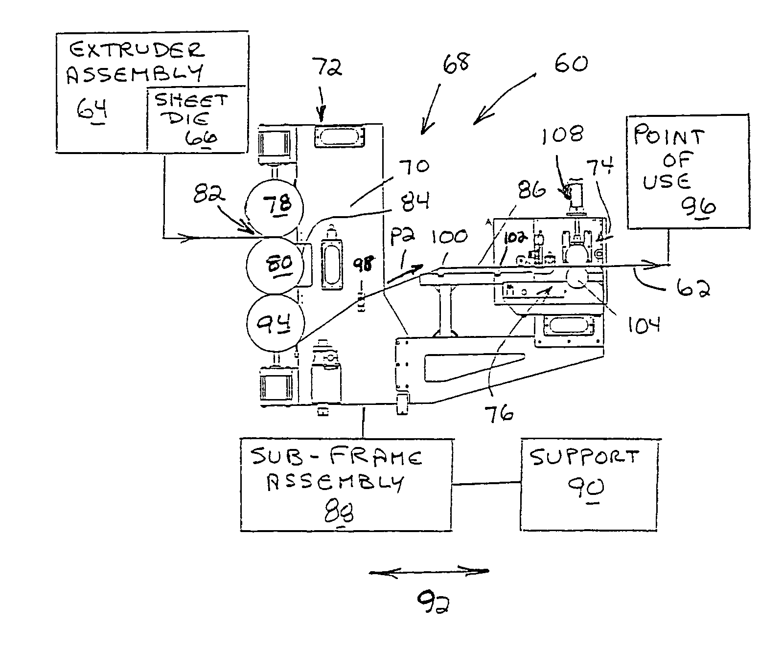
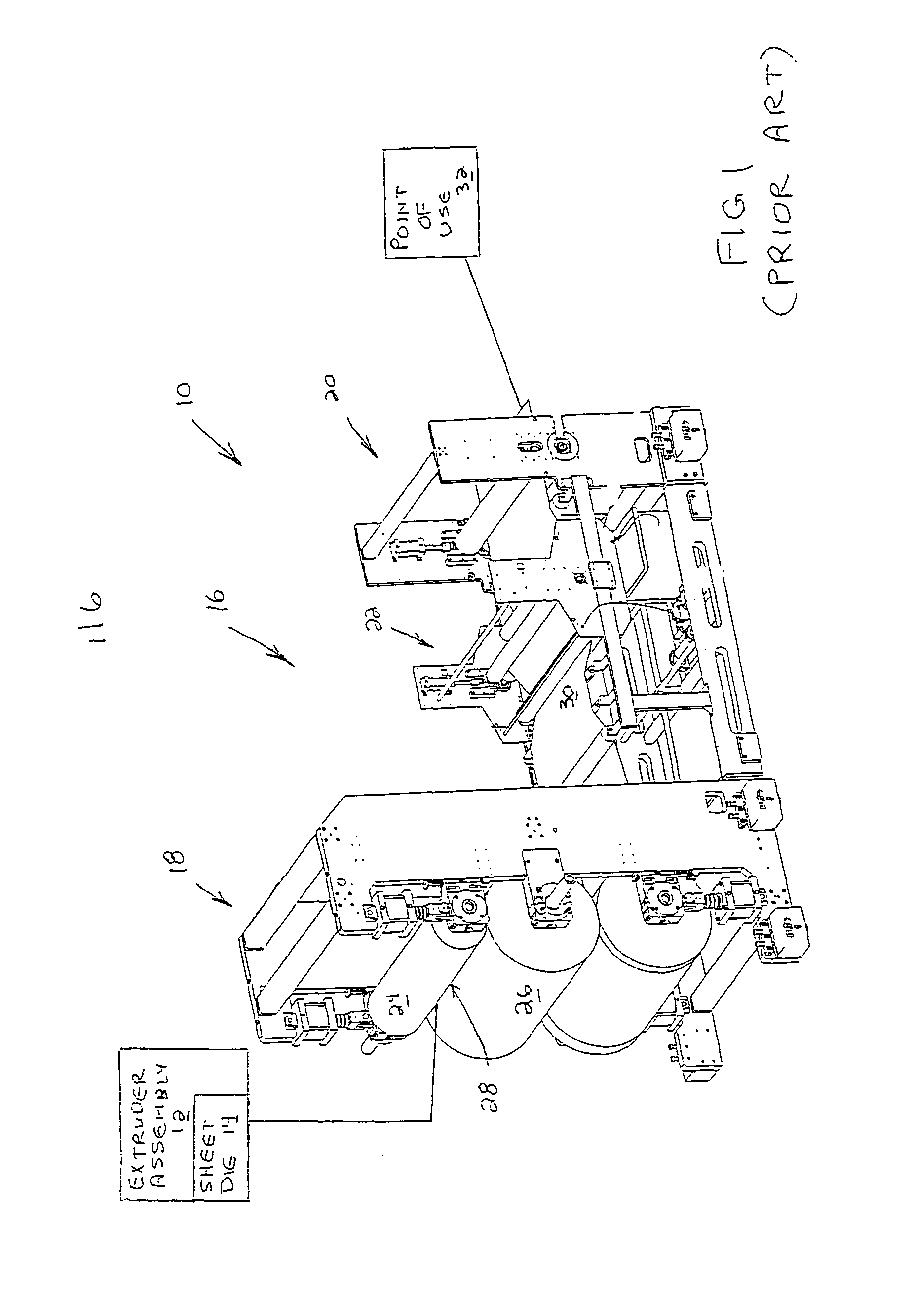
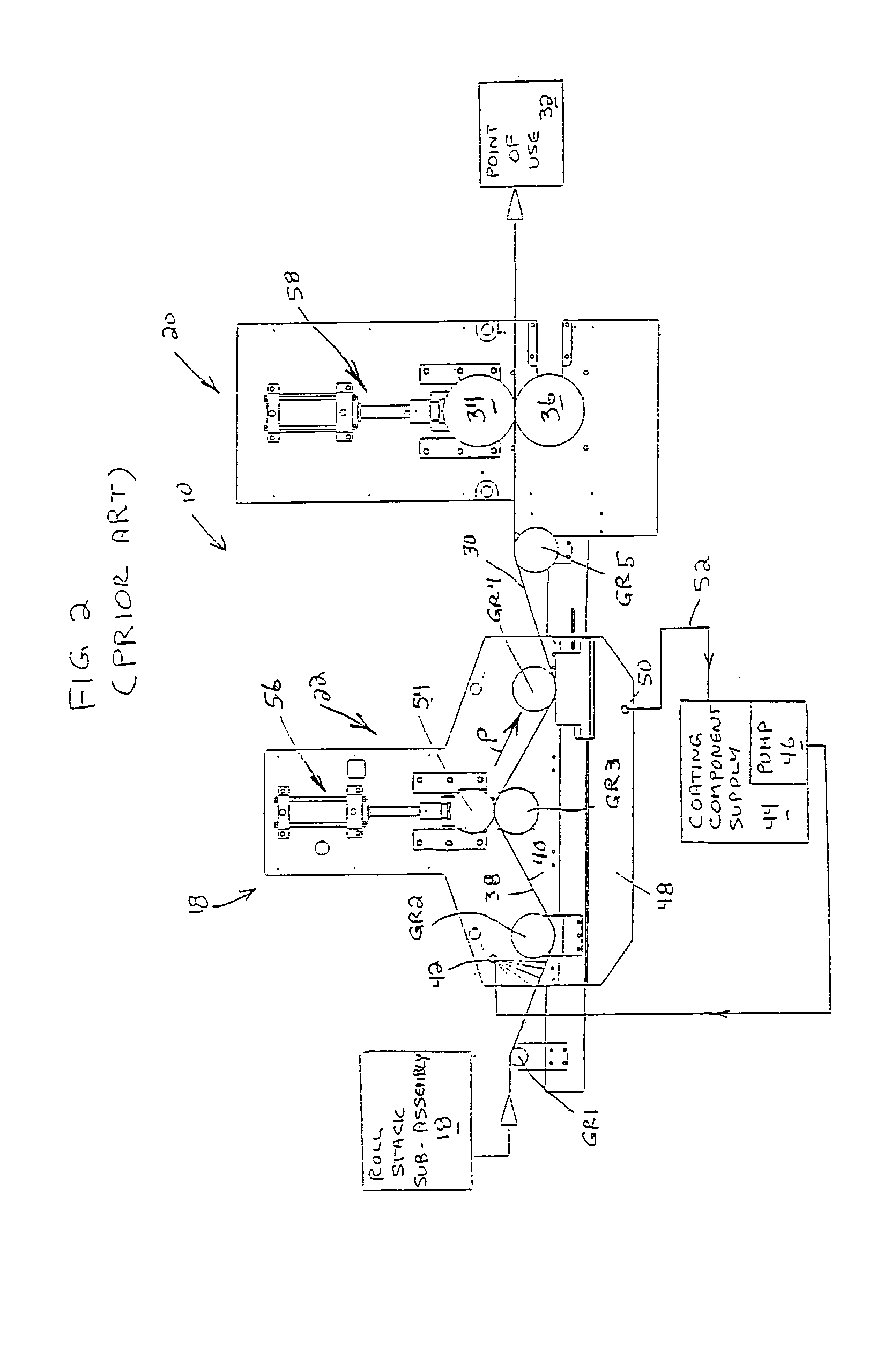
[0044]In FIGS. 1 and 2, a conventional apparatus is shown at 10 for continuously extrusion forming a sheet product. The apparatus 10 consists of an extruder assembly 12 with a sheet die 14 through which flowable material is delivered to a roll stand assembly at 16. The roll stand assembly 16 consists of a roll stack sub-assembly 18, a sheet take-off sub-assembly 20, and a coating system at 22.

[0045]The roll stack sub-assembly 18 consists of first and second rolls 24, 26 between which a nip / lamination location at 28 is defined. Flowable material is delivered from the extruder assembly 12 through the sheet die 14 to the nip location 28. The flowable material is formed, through cooperation between the rolls 24, 26, into a sheet layer that makes up all or part of a sheet product that is delivered downstream to a point of use 32 at which the end sheet product is appropriately handled, as by being rolled, stored, staged, or further processed into another form.

[0046]A sheet layer 30 is cau...


PUM

PropertyMeasurementUnit
forceaaaaaaaaaa
flexibilityaaaaaaaaaa
thicknessaaaaaaaaaa

Abstract

An apparatus for extrusion forming a sheet product having an extruder assembly with a sheet die through which a flowable material is delivered and a roll stand assembly made up of a roll stack sub-assembly and a sheet take-off sub-assembly. The roll stack assembly has first and second rolls between which a nip location is defined at which flowable material from the sheet die is delivered. The sheet take-off sub-assembly produces an advancing force upon a first sheet component made up of at least the first sheet layer. The roll stand assembly further has a coating system for applying a coating component to a surface on at least one sheet component advancing through the apparatus. The roll stand assembly is constructed to be reconfigured thereby to change a path traveled by the at least one sheet component and facilitate selective application of the coating component.

Description

BACKGROUND OF THE INVENTION[0001]1. Field of the Invention[0002]This invention relates to apparatus for extrusion forming sheet products and, more particularly, to a system for selectively applying a coating to one or more sheet surfaces during sheet product formation.[0003]2. Background Art[0004]There is a multitude of different apparatus used to continuously form sheet products made up of one or more extrusion-formed sheet layers. In one exemplary apparatus, an extrusion assembly, through a sheet die, delivers flowable material to a nip / lamination location between adjacent and cooperating rolls on a roll stand assembly. The roll stand assembly may consist of separate sub-assemblies that cooperate to draw formed sheet layers in a downstream direction ultimately towards a point where the completed sheet product is appropriately handled, as by being packaged, staged, etc. One of the sub-assemblies is a roll stack sub-assembly made up of at least the aforementioned two rollers, defini...

Claims


Application Information

Patent Timeline
Patent Type & Authority Patents(United States)
IPC IPC(8): D06B15/02B29C48/92
CPCB29C37/0067B29C47/92B29C47/0038B05C3/10B05C3/125B05C11/04B29C47/0021B29C47/025B29C47/065B29C43/22B29C48/92B29C48/08B29C48/001B29C48/154B29C48/21B29C2948/92647B29C2948/92923
Inventor HANSON, DANA R.GRITZNER, MITCHELL L.LEOPOLD, RYAN E.
Owner PROCESSING TECH
Why Eureka
Try Eureka