Light emitting diode module, and light fixture and method of illumination utilizing the same

a technology of light emitting diodes and light fixtures, applied in the field of light and luminaires, can solve the problems of reducing the amount of lumens (or candlepower) produced by optics, wasting a good portion of light emitted by leds, and being difficult to configure to achieve the desired illumination direction or pattern, etc., to achieve accurate aiming of light output and facilitate the effect of increasing candlepower

Active Publication Date: 2013-01-01
HUBBELL LIGHTING INC
View PDF61 Cites 40 Cited by
  • Summary
  • Abstract
  • Description
  • Claims
  • Application Information

AI Technical Summary

Benefits of technology

[0007]Accordingly, exemplary embodiments of the present invention address at least the above-noted needs by providing an LED module and array of LED modules, as well as a light fixture and illumination methods that facilitate an increase in candlepower and accurate aiming of light output by LEDs onto the surface to be illuminated.
[0009]A further object of the present invention is to provide a unique LED board with at least three diodes positioned horizontally with a quick connection for promoting ease of assembly.
[0011]Yet another object of the present invention is to provide an LED module for creating multiple distinct lighting distributions wherein the center beam exits the luminaire at an angle of about 70° from the carrier plate when the carrier plate is substantially parallel to the surface to be illuminated.
[0012]A further object of the present invention is to provide an LED module that is easily replaceable and environment-friendly to eliminate the need to replace an entire fixture when an LED no longer emits light.

Problems solved by technology

LEDs perform well in the industry, but there are often problems with aiming of the light output from LEDs in a desired direction and pattern.
Consequently, a good portion of light emitted by an LED can be wasted because it is not directed towards a desired area of illumination.
Such control optics tend to decrease the amount of lumens (or candlepower) produced by any given fixture utilizing LEDs because of the loss of lumens through the lens or prism material.
Other conventional means for directing light emitted by LEDs include use of reflective surfaces which, while avoiding light losses suffered by lenses and prisms, may be more difficult to configure to achieve the desired illumination direction or patterns.

Method used


Image

  • Light emitting diode module, and light fixture and method of illumination utilizing the same
  • Light emitting diode module, and light fixture and method of illumination utilizing the same
  • Light emitting diode module, and light fixture and method of illumination utilizing the same

Examples


Embodiment Construction

[0044]Several embodiments of the present invention will now be described in detail with reference to the annexed drawings. In the following description, a detailed description of known functions and configurations incorporated herein has been omitted for conciseness and clarity.

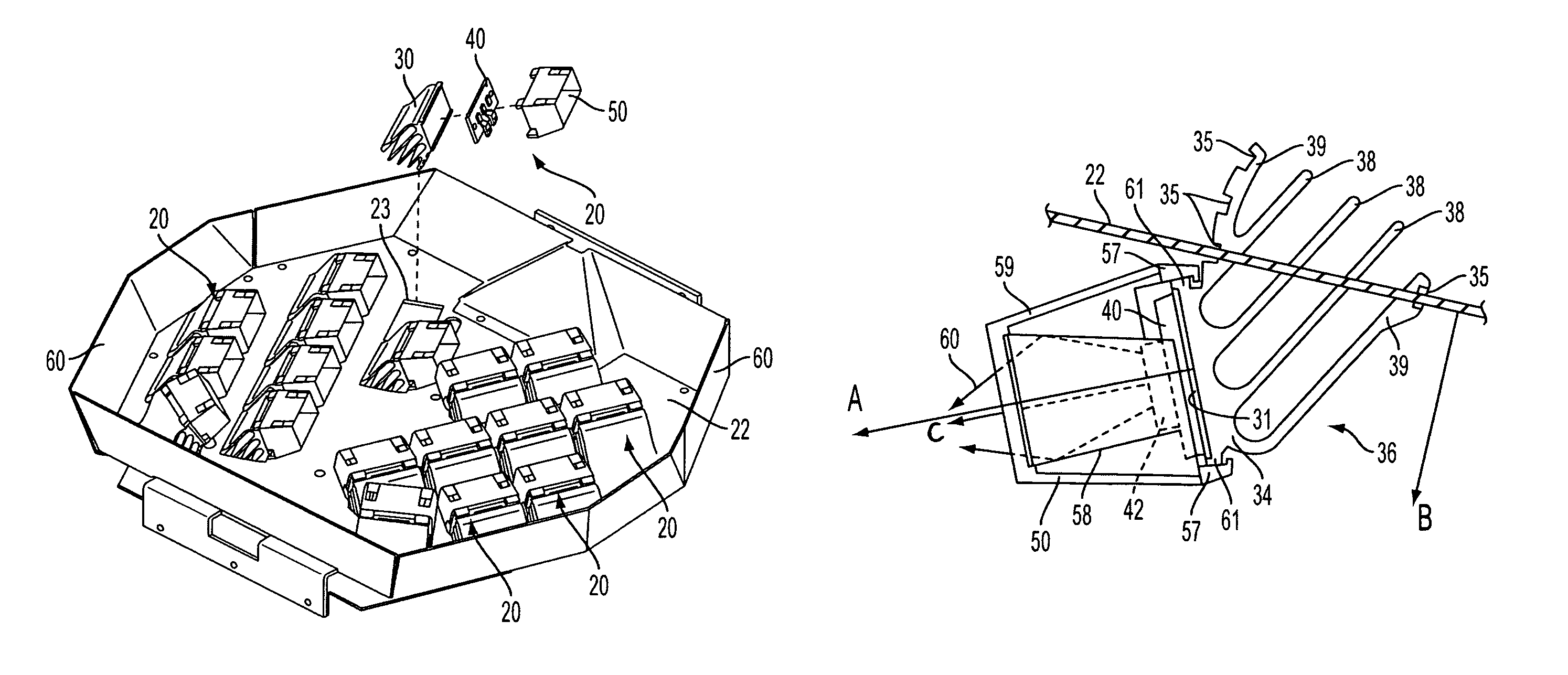
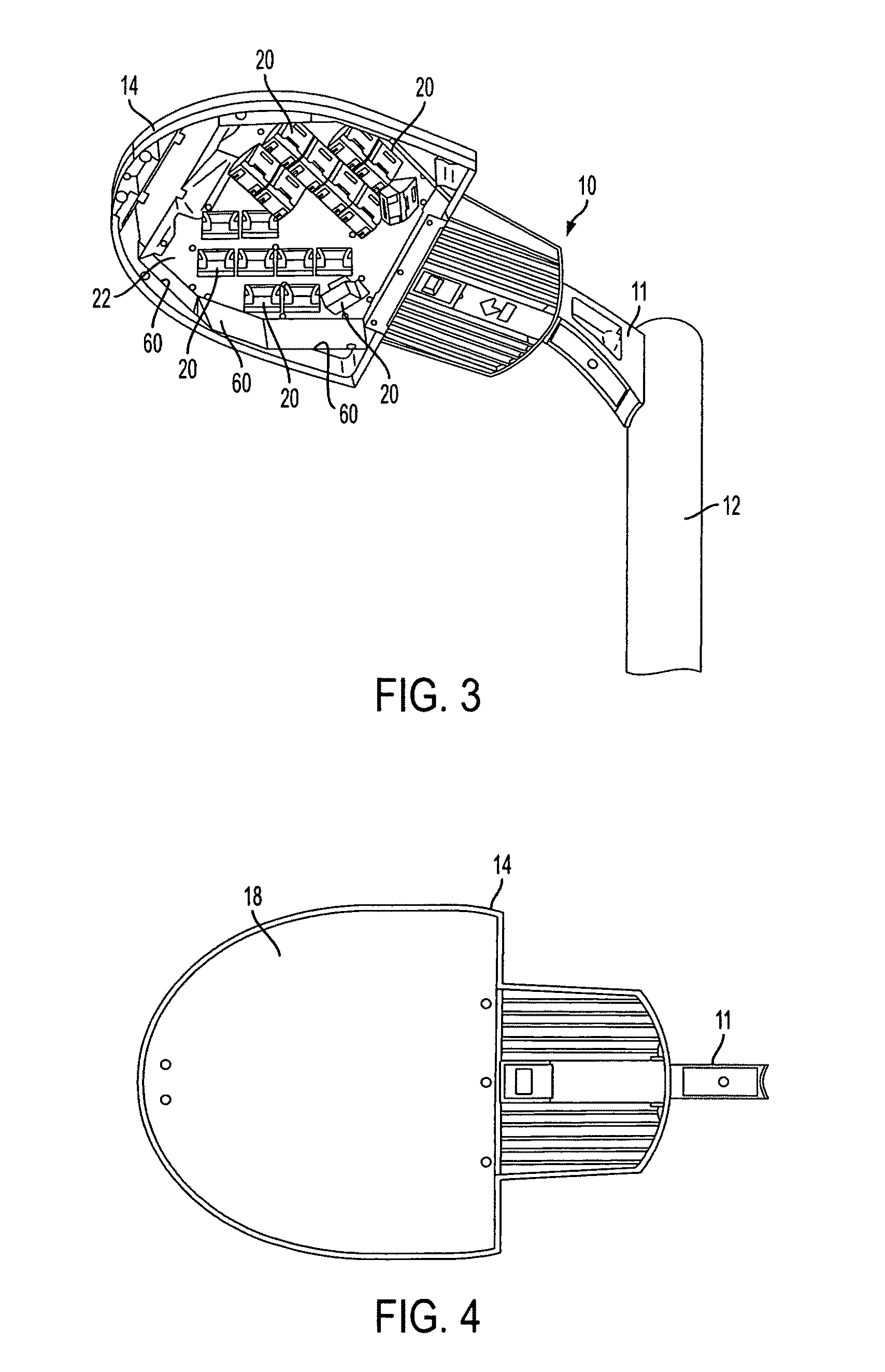
[0045]Turning to FIGS. 1-3, according to an exemplary embodiment of the present invention, it may be desirable to configure a luminaire 10 to emit light at an angle of approximately 70° with respect to the surface 16 to be illuminated, as shown in FIG. 1. In an exemplary implementation, such a luminaire 10 may include pole or support structure 12 and housing 14 that accommodates, as illustrated in the examples of FIGS. 2-4, an LED array having LED modules 20. The housing 14 may include a transparent cover 18 (shown in FIG. 4) that protects the LED array.

[0046]Assuming, for simplicity of explanation only, that a davit arm 11 extends the housing 14 away from pole 12 by a negligible distance, then the direction ...


PUM


Abstract

LED module, arrays of LED modules, luminaires incorporating such arrays, and methods of illumination where the configuration of respective components facilitates any one or more of desired angle, location and shape of illumination provided by the LEDs. LED modules are selectively disposed on a carrier plate. Each of the LED modules includes a substantially planar LED circuit board with LED chips disposed thereon, a heat sink formed of heat transmitting material and having a mounting surface for accommodating an LED circuit board to dissipate heat from the LED chips, and a reflector with its reflective surface disposed with respect to the LED chips to direct the emitted light toward an axis of illumination extending away from and substantially perpendicular to a plane containing the planar LED circuit board. The heat sink, the LED circuit board and the reflector are arranged such that the axis of illumination is not perpendicular to a plane containing the surface illuminated by the light emitted from the LED chips.

Description

FIELD OF THE INVENTION[0001]The present invention is generally in the field of lighting and luminaires utilizing light emitting diodes (LEDs) to facilitate desired illumination. More particularly, the invention provides an LED module, arrays of LED modules, luminaires incorporating such arrays, and methods of illumination where the configuration of respective components facilitates any one or more of desired angle, location and shape of illumination provided by the LEDs.BACKGROUND[0002]Recently, commercial, as well as residential, lighting applications have been transitioning to the use of LEDs where arrays of LED modules provide illumination in applications such as street lighting, office building lighting, and many other outdoor and indoor applications.[0003]LEDs perform well in the industry, but there are often problems with aiming of the light output from LEDs in a desired direction and pattern. In general, LEDs emit light in all directions away from the circuit board thereof. C...

Claims


Application Information

Patent Timeline
Patent Type & Authority Patents(United States)
IPC IPC(8): F21V1/00
CPCF21S2/005F21S8/086F21V7/09F21V29/004F21K9/00F21V29/745F21V29/75F21V29/76F21V19/001F21W2131/10F21W2131/105F21Y2101/02F21Y2103/003F21W2131/103F21Y2113/00F21K9/20F21Y2103/10F21Y2115/10
Inventor LUEKEN, THOMAS C.NEUER, MICHAEL S.
Owner HUBBELL LIGHTING INC
Why Eureka
Try Eureka