Camera accessory, camera body, and camera system

a technology for cameras and accessories, applied in the field of cameras accessories, camera bodies and camera systems, can solve problems such as bound to be complicated structur

Inactive Publication Date: 2013-01-01
NIKON CORP
View PDF11 Cites 20 Cited by
  • Summary
  • Abstract
  • Description
  • Claims
  • Application Information

AI Technical Summary

Benefits of technology

[0014]A camera body according to an eighth aspect of the present invention comprises: a mounting device at which a camera accessory that includes a first accessory contact point, a second accessory contact point, a third accessory contact point, a fourth accessory contact point and a fifth accessory contact point is detachably mounted; a first body contact point that is connected with the first accessory contact point while the camera body is engaged with the camera accessory so as to provide an operating voltage supply to the camera accessory; a second body contact point that is connected with the second accessory contact point while the camera body is engaged with the camera accessory so as to allow a clock signal to be output to the camera accessory; a third body contact point that is connected with the third accessory contact point while the camera body is engaged with the camera accessory so as to allow a first data signal to be output to the camera accessory; a fourth body contact point that is connected with the fourth accessory contact point to allow a second data signal from the camera accessory to be input thereat when the camera body is engaged with the camera accessory; a fifth body contact point that is connected with the fifth accessory contact point while the camera body is engaged with the camera accessory so as to allow a signal assuming a level corresponding to a first truth value to be input thereat from the camera accessory during a time period in which output operation for the first data signal via the third body contact point and input operation for the second data signal via the fourth body contact point are disallowed; a body-side communication control device that outputs the clock signal from the second body contact point and executes the output operation for the first data signal to output the first data signal to the camera accessory via the third body contact point and the input operation for the second data signal to input the second data signal from the camera accessory via the fourth body contact point in synchronization with the clock signal; and an engagement / disengagement detection device that detects disengagement of the camera accessory when the fifth body contact point sustains a signal level corresponding to the first truth value continuously over a length of time equal to or greater than a predetermined time length, wherein: the body-side communication control device receives, via the fifth body contact point, a signal that does not sustain the signal level corresponding to the first truth value continuously over a length of time equal to or greater than the predetermined length of time when the camera accessory is mounted at the mounting device.

Problems solved by technology

There is an issue with the engagement / disengagement detection mechanism disclosed in the publication in that its structure is bound to be complicated.

Method used


Image

  • Camera accessory, camera body, and camera system
  • Camera accessory, camera body, and camera system
  • Camera accessory, camera body, and camera system

Examples


first embodiment

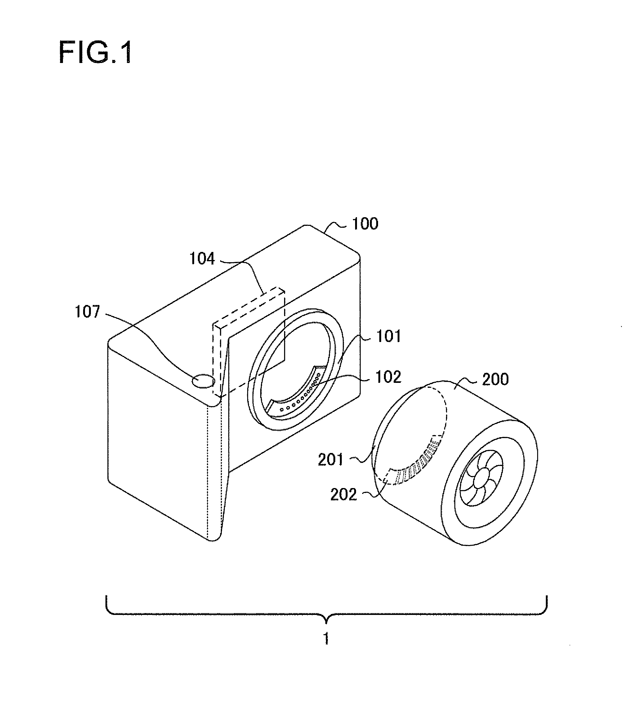
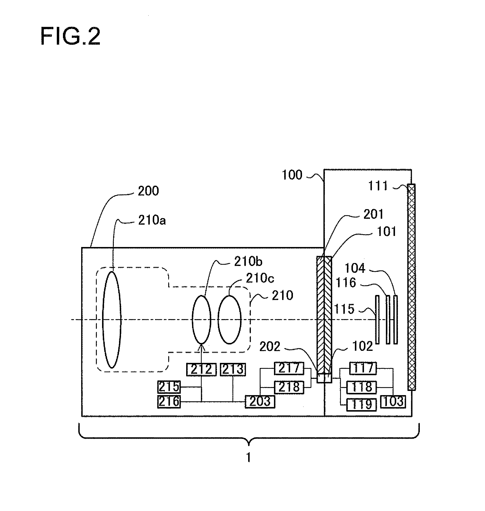
[0033]FIG. 1 is a perspective of a camera system used in conjunction with exchangeable lenses, achieved in the first embodiment of the present invention. It is to be noted that FIG. 1 shows components pertaining to the present invention only, and that illustrations and descriptions of components not directly related to the present invention are not provided. A camera system 1 comprises a camera body 100 and an exchangeable lens (interchangeable lens, or photographic lens) 200 that can be detachably mounted at the camera body 100.

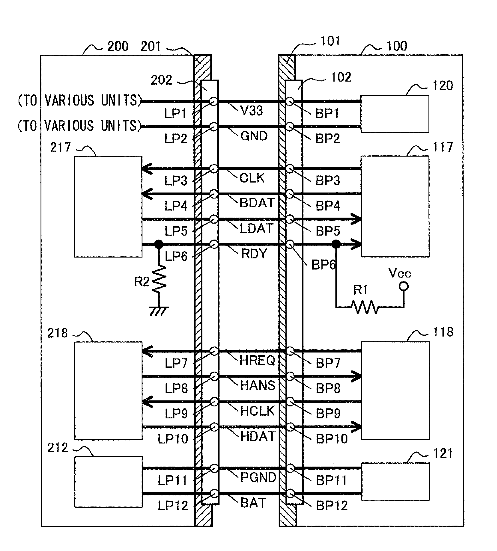
[0034]A body-side mount unit 101, at which the exchangeable lens 200 is detachably mounted, is disposed at the camera body 100. A portion that projects out along part of the inner circumference of the body-side mount unit 101 is provided at a position near the body-side mount unit 101 (on the inner circumferential side of the body-side mount unit 101) at the camera body 100 so as to be used as a holding portion (electrical connection portion) 102 that holds ...

second embodiment

[0103]FIG. 7 is a perspective of the camera system achieved in the second embodiment. A camera system 2 achieved in this embodiment comprises a camera body 100, a middle adapter 700 that can be detachably mounted at the camera body 100 and an exchangeable lens 600 that can be detachably mounted at the middle adapter 700. It is to be noted that in the following description, members and the like identical to those in the first embodiment will be assigned with the same reference numerals as in the first embodiment, so as to preclude the necessity for a repeated explanation thereof.

[0104]The exchangeable lens 600 is compatible with a camera body having mount specifications thereof different from those of the camera body 100. In other words, a lens-side mount unit 601 of the exchangeable lens 600 conforms to mount specifications different from those of a body-side mount unit 101 at the camera body 100, and thus the exchangeable lens 600 cannot be mounted at the camera body 100. In additi...


PUM


Abstract

A camera accessory is detachably mounted at a camera body that includes a first body contact point, a second body contact point, a third body contact point, a fourth body contact point and a fifth body contact point and detects disengagement of the camera accessory when the fifth body contact point sustains a signal level corresponding to a first truth value continuously over a length of time equal to or greater than a predetermined time length. In the camera accessory, the accessory-side communication control device executes control so as to ensure that the signal assuming a level corresponding to the first truth value is not continuously output from the fifth accessory contact point any longer than the predetermined time length while the operating voltage supply from the camera body is provided via the first accessory contact point.

Description

[0001]This non-provisional application claims the benefit of U.S. Provisional Application No. 61 / 554,672 filed Nov. 2, 2011. This application also claims priority from Japanese Patent Application No. 2011-039430 filed Feb. 25, 2011, and Japanese Patent Application No. 2011-189736 filed Aug. 31, 2011. The disclosures of each of the earlier applications are incorporated herein by reference in its entirety.BACKGROUND OF THE INVENTION[0002]1. Field of the Invention[0003]The present invention relates to a camera accessory, a camera body and a camera system.[0004]2. Description of Related Art[0005]A camera system known in the related art may include contact points to enable communication between the camera body and an exchangeable lens (photographic lens). In such a camera system, engagement / disengagement of the exchangeable lens may be detected via the communication contact points. For instance, Japanese Laid Open Patent Publication No. H8-95144 discloses a camera system that detects eng...

Claims


Application Information

Patent Timeline
Patent Type & Authority Patents(United States)
IPC IPC(8): G03B17/00
CPCG02B7/08G02B7/14G03B7/20G03B17/14G03B17/565H04N5/2251H04N5/23209G03B17/00G03B2217/18G03B2206/00H04N23/51H04N23/663H04N23/65
Inventor IMAFUJI, KAZUHARUOIKAWA, MASAFUMI
Owner NIKON CORP
Why Eureka
Try Eureka