Eureka AIR delivers breakthrough ideas for toughest innovation challenges, trusted by R&D personnel around the world.

Measurement Assisted Aerodynamic State Estimator

a technology of aerodynamic state estimation and measurement assisted, which is applied in the direction of instruments, analogue processes for specific applications, and reradiation, etc., can solve the problems of providing the accuracy necessary, adversely affecting the safe operation of the aircraft, and difficulty in safely performing maneuvers

Inactive Publication Date: 2013-11-21
OPTICAL AIR DATA SYST
View PDF20 Cites 22 Cited by
  • Summary
  • Abstract
  • Description
  • Claims
  • Application Information

AI Technical Summary

Benefits of technology

The patent text describes an invention that solves the problem of accurately measuring various flight parameters throughout an aircraft's entire flight envelope. The invention uses an aerodynamic state estimator that receives measurement assistance to produce highly accurate state parameter measurements. This is important for ensuring the safe operation of the aircraft and its ability to perform maneuvers with high precision. The invention also addresses the issues of inefficiency and calibration issues associated with conventional pitot tubes and alpha / beta vanes used for measuring various flight parameters. The technical effect of the invention is to provide an improved solution for accurately estimating the aerodynamic state of an aircraft and ensuring its safe operation.

Problems solved by technology

However, using only the pitot tubes and alpha / beta vanes does not provide the accuracy necessary to expand the performance capabilities of new (fly-by-wire) aircraft, and are susceptible to environmental factors causing them to adversely affect the safe operation of the aircraft.
This is becoming problematic since more and more aircraft require active control faster than it can provide new data.
Therefore, aircraft using pitot tubes and traveling faster than the speed of sound are finding it difficult to safely perform maneuvers because real time actual measurement can no longer be accurately obtained.
The measurement delay associated with these pitot tubes is also an issue as aircraft manufactured with higher performance capabilities, higher maneuverability, and fly-by-wire control (automated aircrafts) require stricter tolerances in their measurement time and accuracy.
As the delay becomes longer and longer with increased speed of the aircraft, automated flight control systems responsible for adjusting the actual control surfaces of the aircraft are becoming out of phase with what the aircraft is actually doing.
Therefore, aircraft designed for stealth capabilities are limited by this inherent deficiency of pitot tubes.
Further, the portion of these pitot tubes that extends out from the aircraft generally creates drag, thereby resulting in the aircraft becoming less aerodynamic.
Other problems can arise from using pitot tubes.
For example, pitot tubes can have calibration issues.
In particular, because these pitot tubes are installed very close to the aircraft (e.g., within a boundary layer), they are adversely affected by disturbed airflow around the aircraft.
These pitot tubes also face icing issues resulting from having to fly through clouds and at high altitudes.
This may also adversely affect the calibration of the pitot tubes.
These vanes are similarly inaccurate and inefficient because they also typically use pressure measurements to calculate the various flight parameters.
Therefore, aircrafts that attempt to perform state estimation using these conventional pitot tubes and / or alpha / beta vanes are rendered inefficient.
In particular, due to the aforementioned deficiencies of conventional pitot tubes and alpha / beta vanes, accurate state estimation may require periodic highly accurate state parameter measurements to be taken.
Performing state estimation using these conventional pitot tubes and / or alpha / beta vanes, without receiving periodic highly accurate measurements, may not be sufficiently accurate to cause a conventional Kalman filter to converge.
Therefore, using only the pitot tubes and alpha / beta vanes to perform state estimation of an aircraft may not provide the necessary accuracy, and thus may adversely affect the safe operation of the aircraft.

Method used


Image

  • Measurement Assisted Aerodynamic State Estimator
  • Measurement Assisted Aerodynamic State Estimator
  • Measurement Assisted Aerodynamic State Estimator

Examples


Embodiment Construction

[0020]The following Detailed Description refers to accompanying drawings to illustrate exemplary embodiments consistent with the invention. References in the Detailed Description to “one exemplary embodiment,”“an exemplary embodiment,”“an example exemplary embodiment,” etc., indicate that the exemplary embodiment described may include a particular feature, structure, or characteistic, but every exemplary embodiment may not necessarily include the particular feature, structure, or characteristic. Moreover, such phrases are not necessarily referring to the same exemplary embodiment. Further, when a particular feature, structure, or characteristic is described in connection with an exemplary embodiment, it is within the knowledge of those skilled in the relevant art(s) to affect such feature, structure, or characteristic in connection with other exemplary embodiments whether or not explicitly described.

[0021]The exemplary embodiments described herein are provided for illustrative purpo...


PUM


Abstract

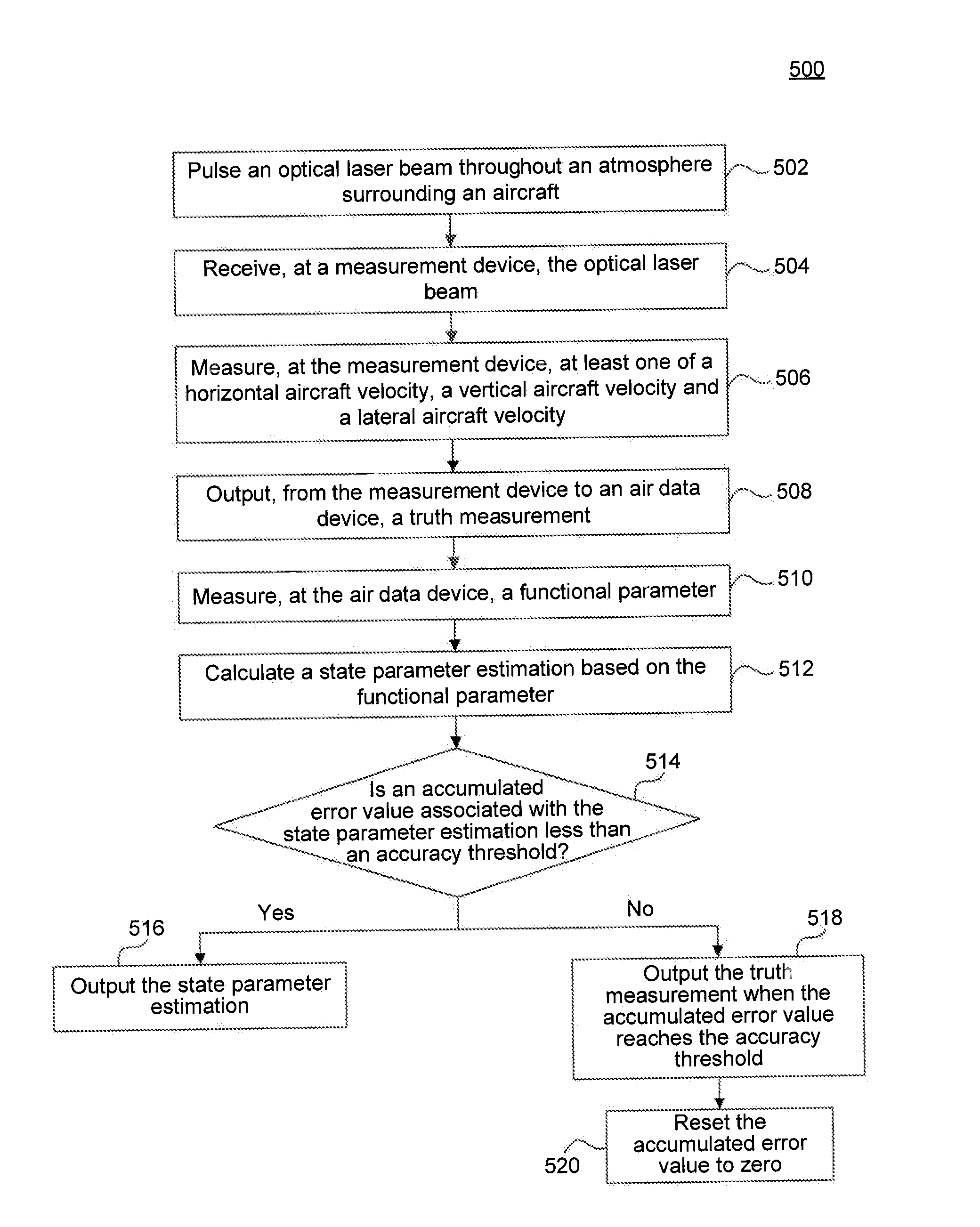
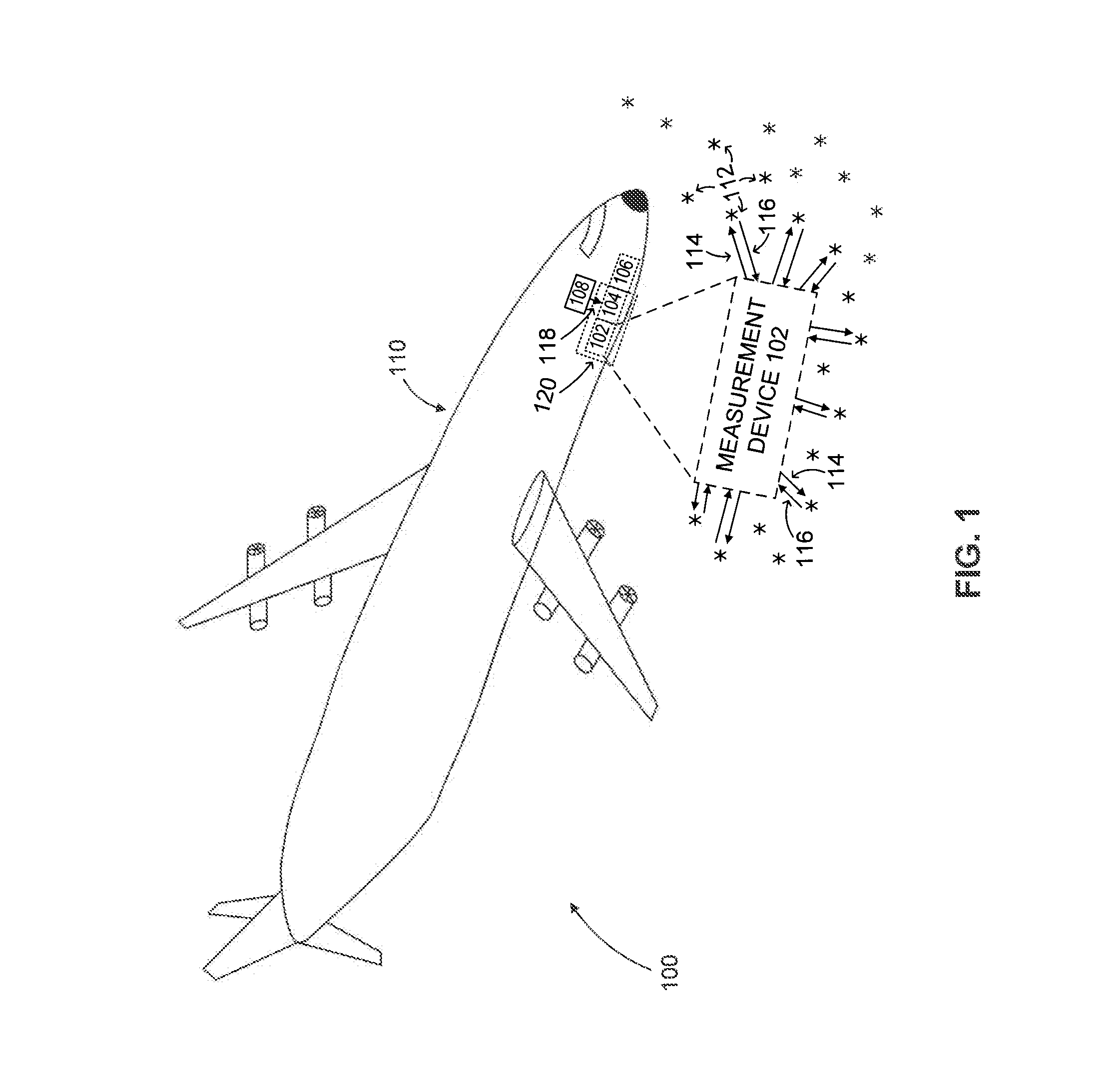
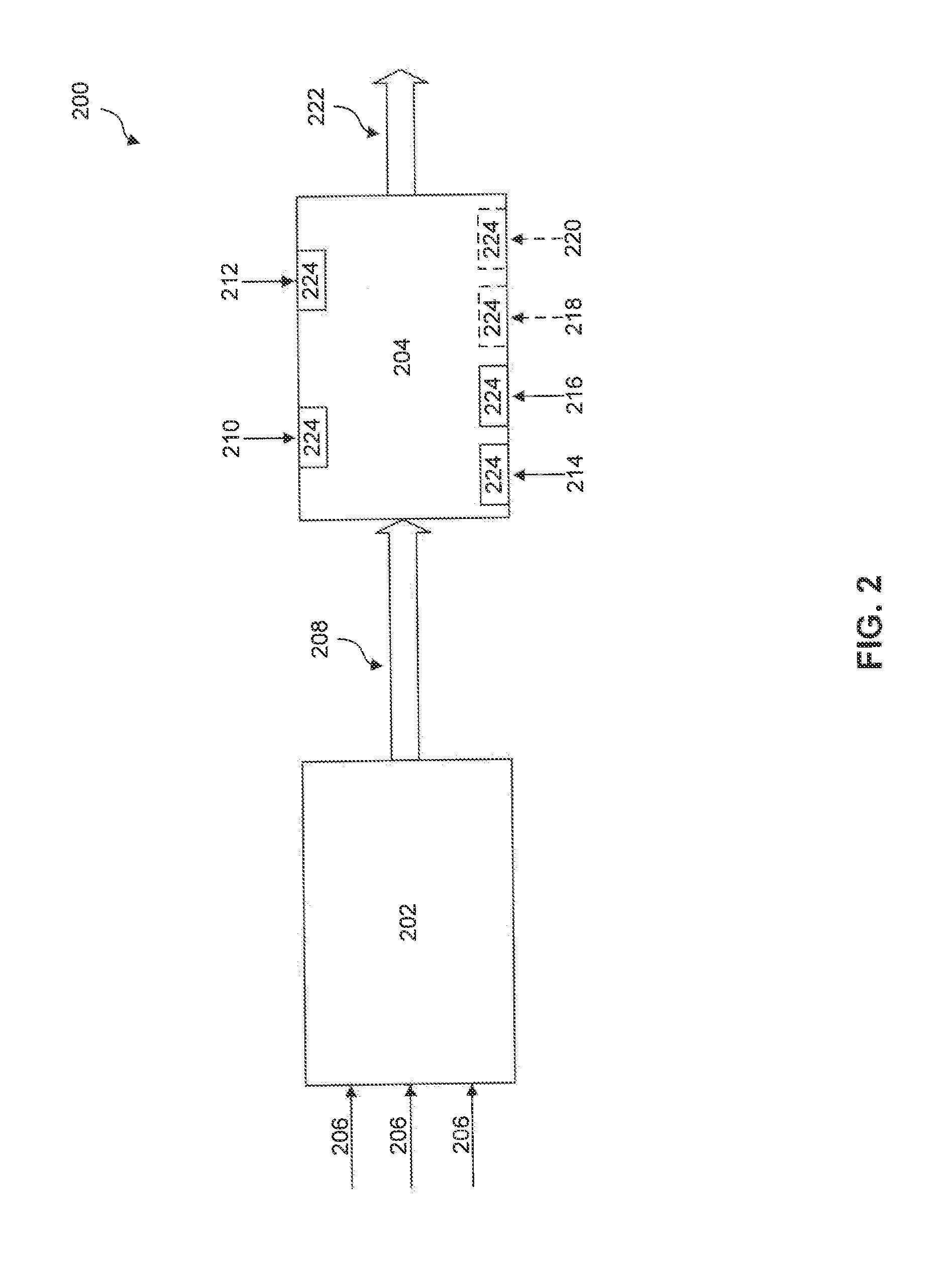
An aerodynamic state estimation system includes a real-time actual measurement device, an air data computer, and a plurality of sensors. The measurement device receives laser scatter energy indicative of one or more atmospheric data parameters and outputs one or more truth measurements. The air data computer module receives the one or more truth measurements, calculates one or more state parameter estimations based on a plurality of functional parameters, and outputs at least one of the one or more truth measurements and the one or more state parameter estimations as one or more high accuracy state parameters, The plurality of sensors, located at the air data computer module, measure the plurality of functional parameters.

Description

BACKGROUND[0001]1. Field of the Invention[0002]The invention generally relates to an aerodynamic state estimator, and more specifically to a measurement assisted aerodynamic state estimator.[0003]2. Related Art[0004]The ability to accurately measure various flight parameters throughout an aircraft's entire flight envelope is important in terms of the safe operation of an aircraft. These various flight parameters include at least the aircraft's airspeed, its angle of attack, its angle of sideslip, and the like. Conventionally, pitot tubes and / or alpha / beta vanes are used to measure these various flight parameters. However, using only the pitot tubes and alpha / beta vanes does not provide the accuracy necessary to expand the performance capabilities of new (fly-by-wire) aircraft, and are susceptible to environmental factors causing them to adversely affect the safe operation of the aircraft.[0005]Pitot tubes are generally configured as an elongated cylindrical tube having a relatively ...

Claims


Application Information

Patent Timeline
Patent Type & Authority Applications(United States)
IPC IPC(8): B64C19/00
CPCG01P5/26G01S17/58G01S17/95Y02A90/10
Inventor ROGERS, PHILIP L.DAKIN, ELIZABETH A.MAMIDIPUDI, PRIYAVADANDAKIN, DANIEL C.
Owner OPTICAL AIR DATA SYST
Why Eureka
Eureka Blog
Learn More