X-ray optical configuration with two focusing elements

a technology of focusing elements and x-ray optical elements, applied in the field of x-ray optical configuration, can solve the problems of affecting the quality of x-ray optical components, the risk of damage or even loss of expensive x-ray optical components during modification and storage, and the disadvantages of the practice of modifying x-ray optical elements, etc., and achieves the effect of simple displacement of slotted apertures and fast switching over

Active Publication Date: 2013-01-01
BRUKER AXS
View PDF3 Cites 1 Cited by
  • Summary
  • Abstract
  • Description
  • Claims
  • Application Information

AI Technical Summary

Benefits of technology

[0021]Switching over between transmission geometry and reflection geometry is thereby facilitated and no time-consuming modifications are required. Switching over is furthermore sufficiently simple that qualified staff are not required.
[0033]In an alternative embodiment of the invention, the aperture system comprises a slotted aperture which can be displaced between two sliding positions. One of the optical paths is thereby blocked by the body of the aperture in each of the two sliding positions and the respective other optical path extends in the area of the slot of the aperture. In this embodiment, switching over between the optical paths can be realized through simple displacement of the slotted aperture.

Problems solved by technology

The modification of X-ray optical elements turns out to be disadvantageous in practice, since the modified X-ray optical elements must be readjusted each time.
This is an extremely time-consuming process which must also be performed by qualified staff.
The expensive X-ray optical components are therefore subjected to an increased risk of being damaged or even getting lost during modification and storage.

Method used


Image

  • X-ray optical configuration with two focusing elements
  • X-ray optical configuration with two focusing elements
  • X-ray optical configuration with two focusing elements

Examples


Embodiment Construction

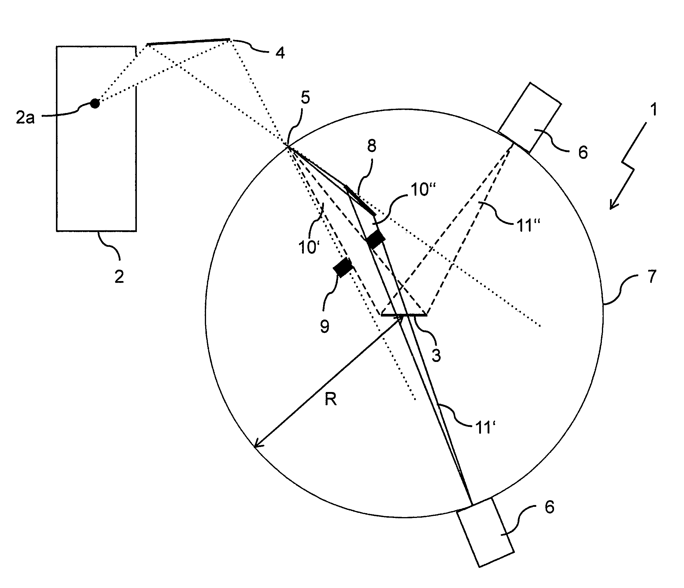
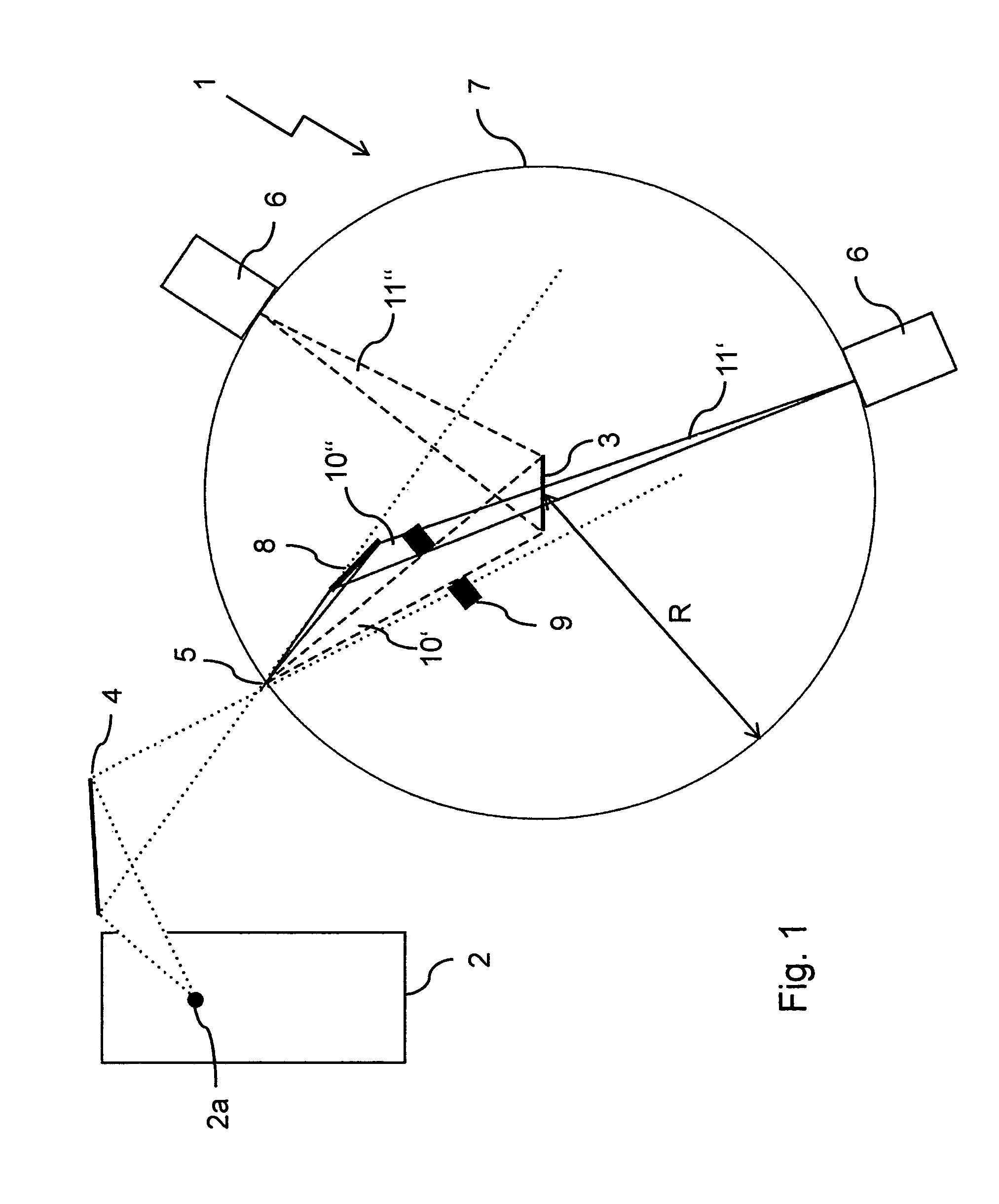
[0042]FIG. 1 schematically shows an inventive X-ray optical configuration 1. X-ray radiation is emitted by an X-ray source 2 with a source focus 2a, and is incident on a first focusing element 4 which initially focuses the X-ray radiation onto an intermediate focus 5. It is preferably positioned on a circular arc 7 with a radius R, on which a detector 6 is also movably disposed.

[0043]Part of the X-ray radiation emanating from the intermediate focus 5 is directly incident, in the form of a first optical path 10′, on the position of the sample 3 where it is reflected by the sample and focused onto the circular arc 7.

[0044]Another part of the X-ray radiation emanating from the intermediate focus 5 is initially incident on a second focusing element 8 and is focused from there in the form of a second optical path 10″ through the position of the sample 3 onto the circular arc 7.

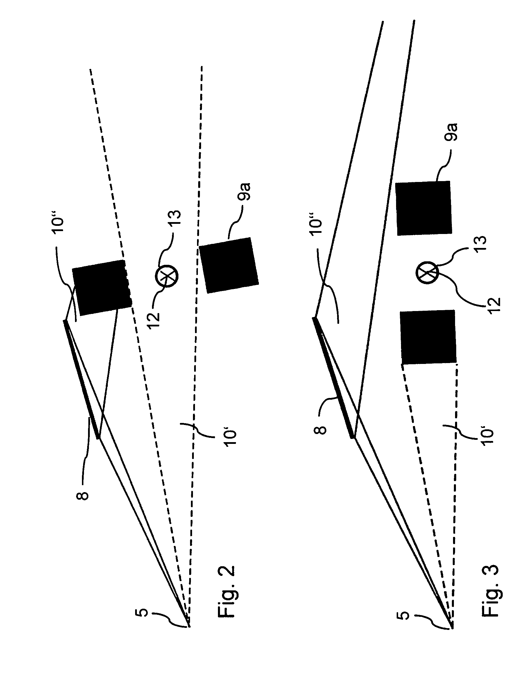
[0045]A switchable aperture system 9 thereby shades one of the two optical paths 10′ or 10″ depending on the mea...


PUM


Abstract

An X-ray optical configuration (1), comprising a position for an X-ray source (2), a position for a sample (3), a first focusing element (4) for directing X-ray radiation from the position of the X-ray source (2) via an intermediate focus (5) onto the position of the sample (3), and an X-ray detector (6) that can be moved on a circular arc (7) of radius R around the position of the sample (3), is characterized in that the configuration also comprises a second focusing element (8) for directing part of the X-ray radiation emanating from the intermediate focus (5) onto the position of the sample (3), and an aperture system (9) for selecting between illumination of the position of the sample (3) exclusively and directly from the intermediate focus (5) (=first optical path (10′)), or exclusively via the second focusing element (8) (=second optical path (10″)). The configuration facilitates changing between reflection geometry and transmission geometry, in particular, wherein modification and adjustment devices are minimized or unnecessary.

Description

[0001]This application claims Paris Convention priority of DE 10 2009 047 672.5 filed Dec. 8, 2009 the complete disclosure of which is hereby incorporated by reference.BACKGROUND OF THE INVENTION[0002]The invention concerns an X-ray optical configuration, comprising[0003]a position for an X-ray source,[0004]a position for a sample,[0005]a first focusing element for directing X-ray radiation from the position of the X-ray source via an intermediate focus onto the position of the sample, and[0006]an X-ray detector which can be moved along a circular arc of radius R around the position of the sample.[0007]An X-ray optical configuration of this type is disclosed in U.S. Pat. No. 6,807,251 B2 and in the leaflet Bruker AXS GmbH; Karlsruhe, Germany, “Diffraction Solutions D8 Advance” 2002.[0008]X-ray diffractometry may be used for diverse analytical tasks, in which different measuring geometries are used, e.g. Bragg-Brentano or parallel beam geometry. This requires, however, different X-ra...

Claims


Application Information

Patent Timeline
Patent Type & Authority Patents(United States)
IPC IPC(8): G21K1/06
CPCG21K1/06G21K2201/064
Inventor OLLINGER, CHRISTOPH
Owner BRUKER AXS
Why Eureka
Try Eureka