Method and apparatus for determining design modification effects on a computerized engineering model

a computerized engineering and effect technology, applied in the field of method and apparatus for determining design modification effects on computerized engineering models, can solve the problems of complex geometry and field problems that require computational intensiveness, take several hours to complete, and affect the accuracy of the results

Active Publication Date: 2013-01-01
WISCONSIN ALUMNI RES FOUND
View PDF10 Cites 0 Cited by
  • Summary
  • Abstract
  • Description
  • Claims
  • Application Information

AI Technical Summary

Benefits of technology

[0007]The present inventors have designed an analytical tool, which can be implemented as software executed by a computer, that assesses the impact of a change in the design of a finite design element with reduced time and computational costs. The analytical tool is applicable with determining the impact of self-equilibrating features, i.e., those features having a localized impact, as well as non-self-equilibrating features, i.e., those features having a global impact. In general, the analytical tool provides feature-specific design sensitivity assessment by performing finite element analysis with a given finite element and then determining the impact any internal or boundary modifications to the finite element without iteratively repeating finite element analysis for the model with each design modification. In this regard, the present invention provides a tool for design exploration that is neither computationally nor time prohibitive.
[0008]For example, the present invention allows a designer interested in increasing the tip displacement within certain design constraints of a cantilever beam to explore multiple design configurations without requiring execution of the complete finite element method (constructing the geometry, creating a finite element mesh, assembling a stiffness matrix, and solving the resulting linear system, for each configuration). First, a conventional finite element analysis is performed on the base design, or the results therefrom accessed, to provide a value for a performance metric, such as elasticity in this example. In this elasticity example, the value of the performance metric represents the deformation (“primary”) field associated with the base design. Next, or contemporaneously with the computation of the primary field, and at insubstantial computation and time cost, an adjoint field for the base configuration is derived. In this elasticity example, the adjoint field corresponds to the deformation field resulting from a unit load being placed on the cantilever. Now, the impact, with respect to tip displacement by the unit load, of a modification in the design of the beam can be derived; and, more importantly, without requiring execution of the complete finite element method. Specifically, boundary regions for a given modification, e.g., a hole formed in the body of the beam, are determined on a suitable coordinate grid and an expression characterizing tip displacement as a function of the primary and adjoint fields is solved to assess the impact of the design modification. More particularly, the expression is integrated over the boundary regions to provide a value (or range of values) for the performance metric, e.g., tip displacement. Thus, the impact of the design modification in terms of the performance metric can be quickly derived without requiring a separate finite element analysis of the design modification. In this regard, the present invention simplifies the assessment of design changes to boundary integral computation and thus effectively bypasses the need for repeated model preparation, meshing, and the like for design exploration.
[0010]Accordingly, it is one object of the present invention to provide a tool available to designers and engineers to quickly and computationally efficiently assess the impact of design modifications to an engineering design.
[0011]It is another object of the present invention to provide an optimization tool that automatically determines an optimized design modification to a base design given a set of constraints.

Problems solved by technology

While a function of the complexity of the model, it is not uncommon for a mesh to take several hours, if not, days to complete.
A particularly challenging implication of such an iterative design process is that the designer must compute various quantities of interest, e.g., such as average stress within a region, maximum deflection, etc., as features and / or parameters are modified.
This can be computationally intensive for complex geometry and field problems.

Method used


Image

  • Method and apparatus for determining design modification effects on a computerized engineering model
  • Method and apparatus for determining design modification effects on a computerized engineering model
  • Method and apparatus for determining design modification effects on a computerized engineering model

Examples


Embodiment Construction

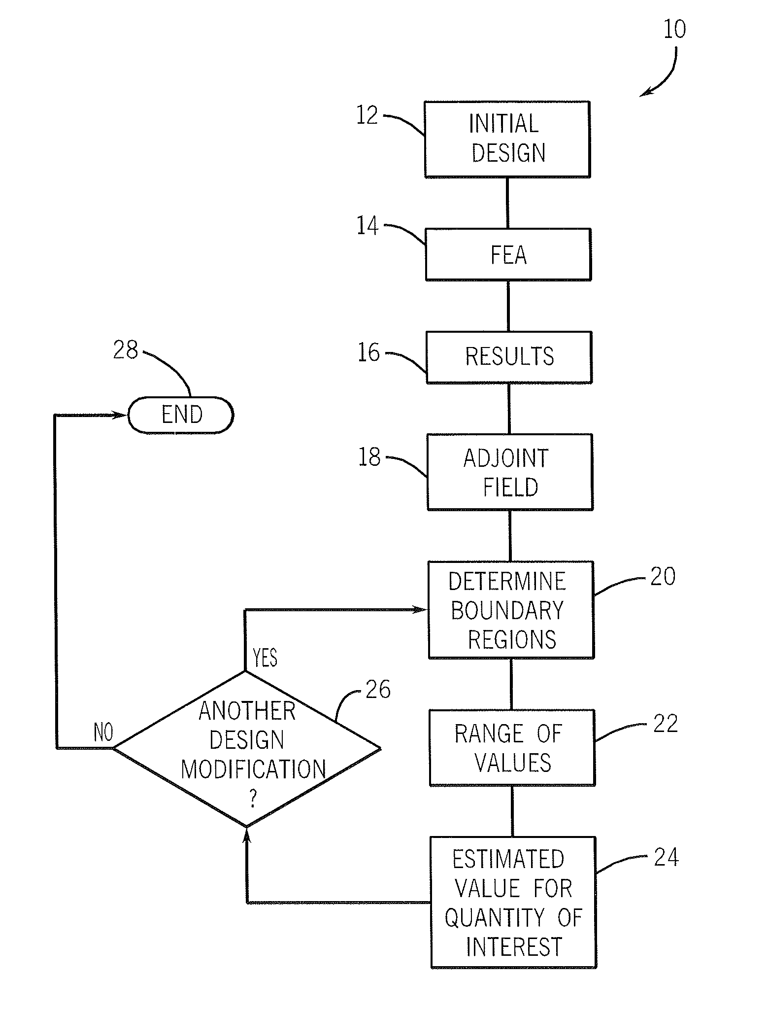
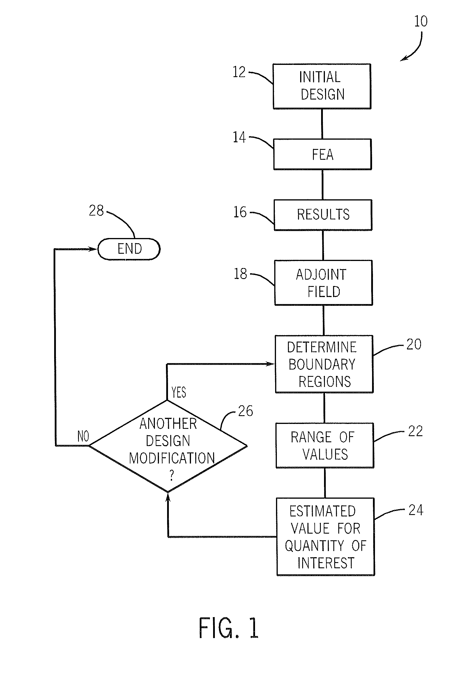
[0020]The present invention is directed to a technique, and hardware / software / firmware for carrying out such a technique, in which the impact of a design change of a finite design element is determined without execution of the finite element method.

[0021]Referring now to FIG. 1, the design exploration process 10 begins with development, or otherwise accessing, an engineering design at block 12. A number of design and development tools, as known in the art, may be used to generate the initial design. Consistent with conventional finite element method, the initial design generated at block 10 is subjected to finite element analysis at block 14. As known in the art, finite element analysis is a computer simulation technique that uses numerical analysis to assess the performance of the design when subjected to various environmental factors. For example, finite element analysis may be performed for a dual device heat block design to assess the weighted temperature within a semiconductor ...


PUM


Abstract

An engineering simulation tool uses boundary regions of proposed design modifications to a finite design element to assess the impact of those proposed design modifications. This tool allows a designer to incorporate a new design feature into a proposed model and generate simulated performance results for the proposed design without re-execution of finite element method.

Description

CROSS-REFERENCE TO RELATED APPLICATION[0001]This application claims the benefit of U.S. Ser. Nos. 60 / 887,229, filed Jan. 30, 2007, and 61 / 024,029, filed Jan. 28, 2008, the disclosures of which are incorporated herein by reference.STATEMENT REGARDING FEDERALLY FUNDED RESEARCH[0002]This invention was made with government support under 0322134 awarded by the National Science Foundation. The government has certain rights in the invention.FIELD OF THE INVENTION[0003]The present invention is directed to a method and apparatus for determining design modification effects on a computerized engineering model. Design modifications include the addition or removal of features, also known as “defeaturing”, within an engineering model. In one implementation, the present invention provides an optimization tool for determining the impact or effect of a new design for a finite design element of a computerized model without requiring engineering analysis, such as finite element analysis, of the entire...

Claims


Application Information

Patent Timeline
Patent Type & Authority Patents(United States)
IPC IPC(8): G06Q40/00
CPCG06F17/5018G06Q10/0639G06F2217/80G06F2119/08G06F30/23
Inventor SURESH, KRISHNANGOPALAKRISHNAN, SANKARA HARI
Owner WISCONSIN ALUMNI RES FOUND
Why Eureka
Try Eureka