Cauterizing system

a catheterizing system and catheterizing rod technology, applied in the field of medical devices, can solve the problems of difficult to comfortably maneuver cautery pencils, cumbersome traditional clamps, difficult to maneuver ecu around surgical sites, etc., and achieve the effects of reducing manufacturing costs, enhancing patient safety, and reducing contamination

Inactive Publication Date: 2013-01-08
FILA RYAN
View PDF8 Cites 13 Cited by
  • Summary
  • Abstract
  • Description
  • Claims
  • Application Information

AI Technical Summary

Benefits of technology

[0008]Some embodiments disclosed herein provide a system with a flexible cord without an appreciable amount of memory that facilitates rapid set-up to decrease the overall surgical time. Reducing the surgical time may reduce risks associated with performing surgery. The system can be mounted on a surface or structure without using complicated clamps, thus enabling physicians, nurses, technicians, and other users to easily mount the system on various types of mounting surfaces or structures.
[0009]Representative embodiments disclosed herein are generally directed towards cauterizing systems and methods of using the same. In particular, a cauterizing system includes a cauterizer handpiece, a main housing, and a deployable handpiece cord extending between the cauterizer handpiece and the main housing. In some aspects, the handpiece cord is an extendable and retractable cord. The extendable and retractable cord can be easily kept away from the surgical site.

Problems solved by technology

This makes it difficult to maneuver the ECU around surgical sites.
Traditional clamps are cumbersome and difficult to use.
It may be difficult to comfortably maneuver cautery pencils throughout a long procedure because cautery pencils are often somewhat bulky and uncomfortable to hold.
Cautery cords are not long enough to permit convenient maneuvering of the cautery pencil about many surgical sites.
If there are multiple working surgical sites, for example, there may be an appreciable risk of pulling the ECU off of the sterile field, thereby disrupting the surgical procedure.
Because cautery pencils are connected to cords that are not readily visually distinguishable from the surrounding environment, difficulties can arise in avoiding interference with the cord.
Additionally, the cautery cord may have a similar appearance to other cords in proximity to the surgical sites and may cause confusion during a surgical procedure.
Thus, it may be difficult to keep track of the cord during a surgical procedure or to see and avoid unwanted contact, pulling, tripping over, and the like.

Method used


Image

  • Cauterizing system
  • Cauterizing system
  • Cauterizing system

Examples


Embodiment Construction

[0047]The following detailed description is generally directed towards medical systems and methods of using the same. Many specific details of certain embodiments of the present disclosure are set forth in the following description and in FIGS. 1-28 to provide a thorough understanding of such embodiments. One skilled in the art, however, will understand that the disclosed embodiments may have additional features or may be practiced without one or more of the details presented in the following description.

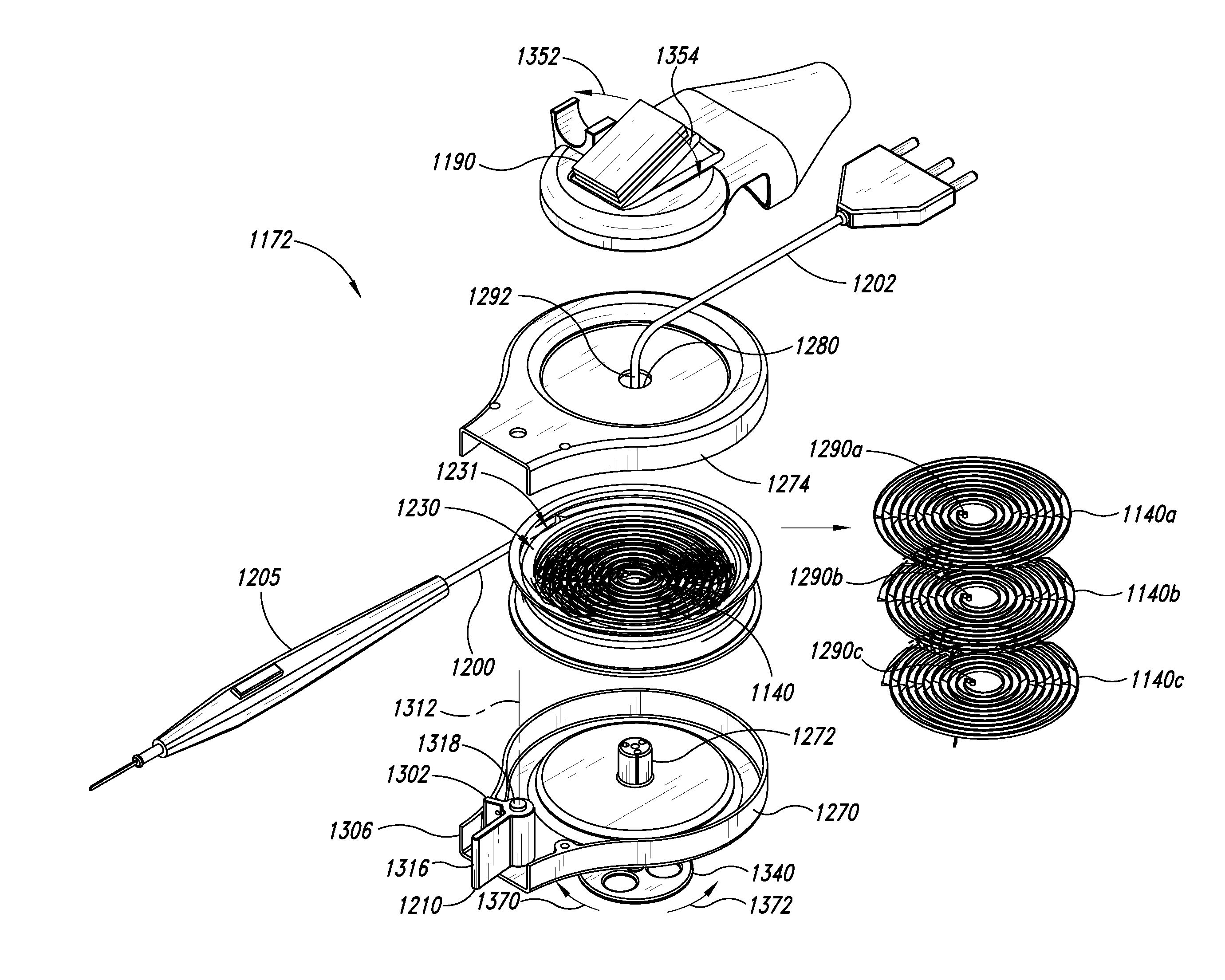
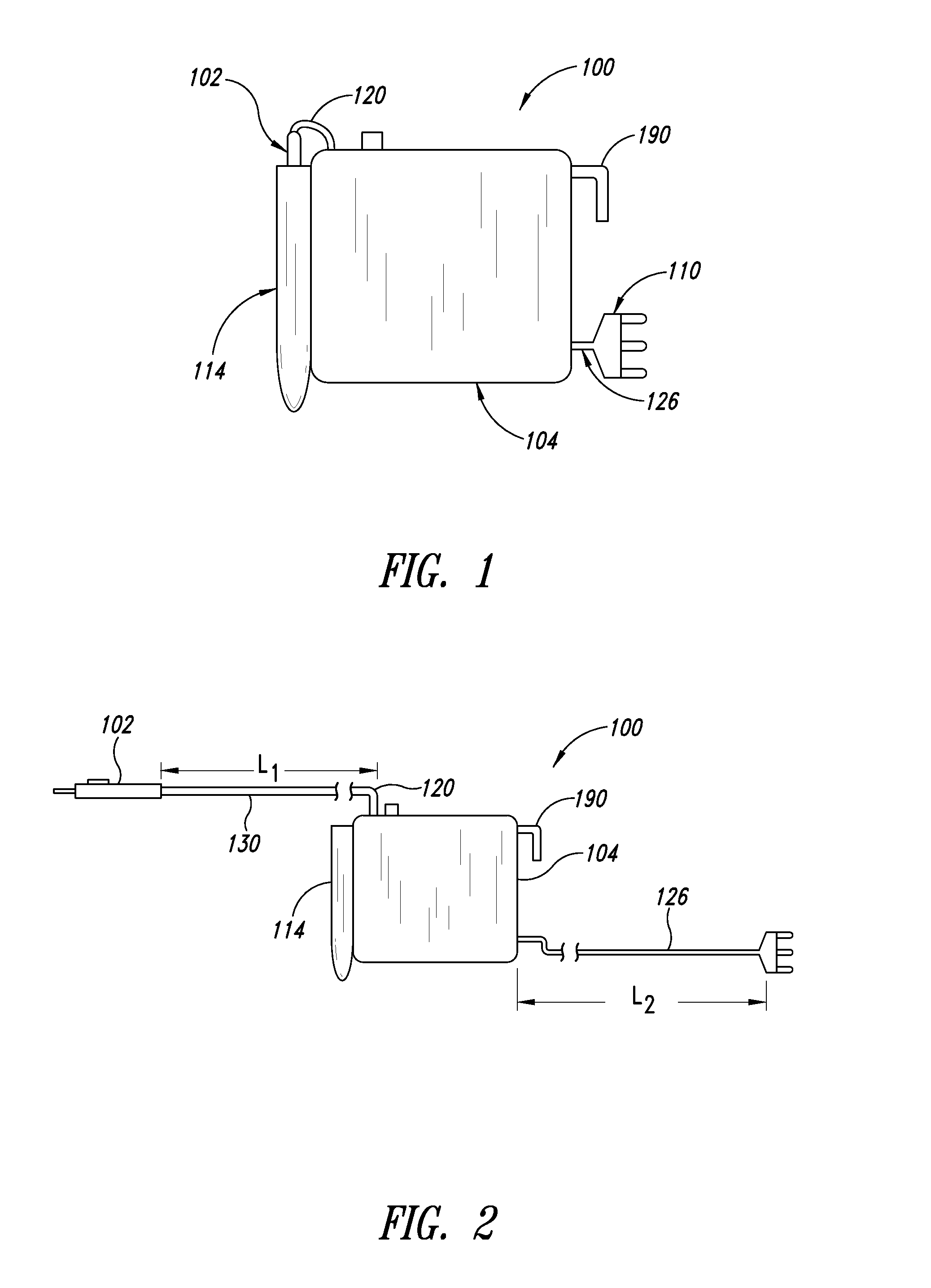
[0048]FIGS. 1 and 2 illustrate a cauterizing system 100 that includes a cauterizer handpiece 102 and a handpiece cord 120 coupling the handpiece 102 to a power source (not shown) and to a cord dispenser 104. The illustrated cauterizer handpiece 102 of FIG. 1 is retained in a holder 114, which is permanently or temporarily coupled to the cord dispenser 104. As shown in FIGS. 1 and 2, the handpiece cord 120 is stored in the cord dispenser 104 and extends between the cauterizer handpie...


PUM

PropertyMeasurementUnit
length L1aaaaaaaaaa
length L1aaaaaaaaaa
length L1aaaaaaaaaa

Abstract

A cauterizing system having a cauterizer tool for performing cauterization procedures, a cauterizer cord for carrying power to the cauterizer tool, a plug and a power cord for carrying power from the plug to the cauterizer cord, and a housing in which is mounted a mechanism for retracting and extending the cauterizer cord and the power cord.

Description

CROSS-REFERENCE TO RELATED APPLICATIONS[0001]This application is a continuation-in-part application of International Application No. PCT / US2007 / 080631, filed on Oct. 5, 2007, which claims priority under 35 U.S.C. §119(e) of U.S. Provisional Patent Application No. 60 / 850,062 filed Oct. 6, 2006. These two applications are incorporated herein by reference in their entireties.BACKGROUND[0002]1. Field[0003]The present disclosure generally relates to medical systems and methods for using the same and, more particularly, to cauterizing systems with one or more deployable cords.[0004]2. Background Discussion[0005]Electrocautery units (ECU) are used in surgery to cauterize tissue in order to control bleeding. A packaged ECU often includes a cautery pencil and a bound up cautery cord extending from the cautery pencil to a plug. Typically, the cautery cord is folded up (e.g., in an accordion type style) such that the cord has an unwanted folded configuration (i.e., a shape memory configuration...

Claims


Application Information

Patent Timeline
Patent Type & Authority Patents(United States)
IPC IPC(8): H02G11/02B21C47/00
CPCA61B18/08B65H75/4431H02G11/02A61B2018/00595B65H2701/34
Inventor FILA, RYANBERGLIN, JOHN SCOTT
Owner FILA RYAN
Why Eureka
Try Eureka